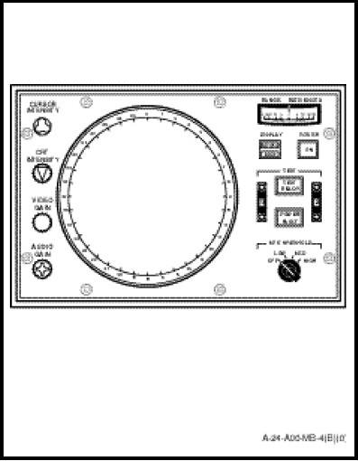
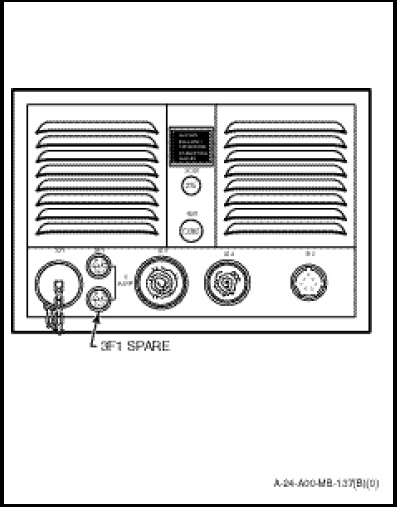
The azimuth and range indicator (Figure 1-12-1) mounted on top of the sonar receiver on the Sonar Operator station, presents the sonar operator with target bearing and range information on a PPI. The indicator is cooled by a blower located in the rear of the indicator. Located on the rear panel is a running time meter, a 115 VAC three phase circuit-breaker, a 5 ampere fuse, a spare fuse and connecting plugs (Figure 1-12-2). Control and indicator functions are as follows:
a. Cathode Ray Tube (CRT). The CRT provides visual display of target echoes or bearing to noise sources in long or short pulses.
b. CURSOR INTENSITY Control. Varies brightness of cursor circle on PPI. The knob shape is clover-leaf and the colour orange.
c. CRT INTENSITY Control. Varies brightness of PPI display. The knob shape is triangular and the colour blue.
d. VIDEO GAIN Control. Varies level of video signals applied to the CRT. The knob shape is a serrated cylinder and the colour red.
e. AUDIO GAIN Control. Varies level of right and left audio signals applied to the sonar operators head-set when SONAR DIRECT is selected on the sonobuoy receiver control panel. The knob shape is a raised cross and the colour violet.
f. RANGE RATE-KNOTS Meter. Indicates opening or closing speed of target in cursor circle in knots during echo-ranging modes and indicates test conditions during built-in test functions.
g. DISPLAY Switch. The DISPLAY indicator push-button switch, hard wired to the SONAR position, provides the necessary power to the receiver, transmitter, and dome control for system operation as a dipping sonar. The BUOY position is not used in this installation.
h. POWER Indicator/Push-button Switch. The illuminated ON position applies 28 VDC to energize the main power to the remaining units of the sonar set. When in the extinguished position it removes the 28 VDC from the sonar set.
i. TEST/READY Indicator/Push-button Switch. When depressed, applies 28 VDC to illuminate the SONAR, BUOY, POWER, FAULT, TEST and READY lamps on the Azimuth and Range Indicator, the ONE, ALL and VERIFY lamps on the Sonar Receiver Control Panel, and the UNSEAT and TRAIL lamps on the Dome Control. It also connects a ground path to illuminate the numeral 8 for all digits of the DEPTH-FEET display on the Dome Control and the numeral 8 for all digits of the BEARING and RANGE-YARDS displays on the Sonar Receiver Control Panel. The TEST indicator illuminates amber when depressed. The READY indicator illuminates green approximately 8.5 seconds after the TEST switches are set to 0-2 or 5-0, or approximate 2.5 seconds after the TEST switches are set to any other position.
j. TEST Switch A. Applies binary coded test A, 0 through 11 signals to built-in test equipment circuits.
k. TEST Switch B. Applies binary coded test B, 0 through 9 signals to built-in test equipment circuits.
l. POWER/FAULT Indicator Push-button Switch. When depressed applies a ground to reset fault circuits in the dome control and power fault circuits in the indicator. The POWER indicator illuminates red when a fault exists in one of the indicator power supplies or if an over temperature condition exists in the indicator. The FAULT indicator illuminates red when a fault exists in the receiver, indicator or transmitter and flashes red when a fault exists in the dome control.
m. MTI THRESHOLD Switch. In the OFF position permits echoes from all targets to be displayed on the PPI. In the LOW position, the PPI displays only targets with range rate in excess of 1 knot. In the MED position, the PPI displays only targets with range rate in excess of 2 knots. In the HIGH position, the PPI displays only targets with range rate in excess of 3 knots.