The control panel (Figure 1-12-14) provides selection of any one of the 31 preset channels and works in conjunction with the ARA selector panel. With the ARA control panel on and selected to the appropriate channel and the ARA selected to OTPI, sonobuoy bearing information will be displayed on the No.1 needle of the BDHI.
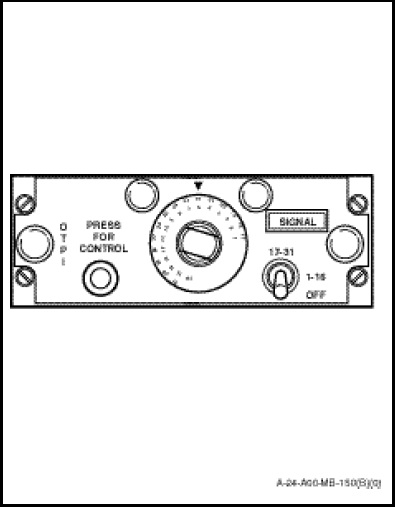
The OTPI control panel contains a signal light, a channel selector, a channel range selector switch and a remote control button. The individual controls and their functions are described as follows:
a. The SIGNAL light is a green capsule which illuminates when the signal transmitted by the sonobuoy has been received and is of sufficient strength to home-in on. At this time, a provision is made for this facility but the green capsule light is permanently off.
b. The channel selector switch is a 16-position rotary switch. The inner portion of the switch is numerically marked “1” to “16” and is used in conjunction with the 1–16 position of the channel range selector switch to provide selection of preset channels 1 to 16. The outer portion of the switch is numerically marked “17” to “31” and is used in conjunction with the 17–31 position of the channel range selector switch to provide selection of preset channels 17 to 31.
c. The channel range selector switch is a three position toggle-switch providing the following functions;
(1) OFF. In this position power is disconnected, with the exception of the 28 VDC edge lighting supply, and the system is inoperative.
(2) 1–16. Preset channels 1 to 16 may be selected on the channel selector switch. Power is applied and the system is operative.
(3) 17–31. Preset channels 17 to 31 may be selected on the channel selector switch.
d. The PRESS FOR CONTROL button is not used.