The system is powered by the DC primary bus and is protected by a DC circuit-breaker marked “GPS” on the overhead circuit-breaker panel. The Trimpack GPS system consists of:
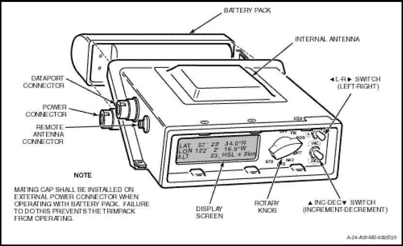
a. GPS Controller/Display. The GPS controller/display is a single unit (Figure 1-11-20) containing a built-in antenna, a receiver section, a digital/computer section, a display, switches for data input, and connections for a rechargeable Nickel/Cadmium (NICAD) battery cell. Connectors are provided for the external antenna, an external power supply and a data communications port. The unit is installed on a tray structure attached immediately forward of the lateral support web of the TACCO’s control console. The tray structure is designed for quick, easy removal (six camlok fasteners) to allow easy access to the CH124 broom closet for maintenance.
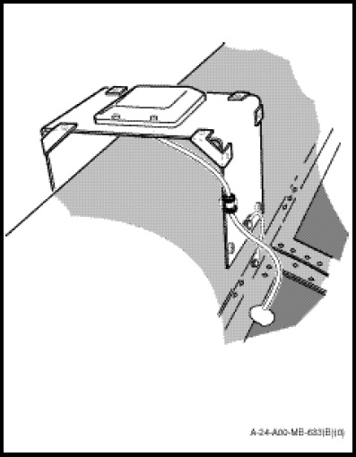
b. GPS External Antenna. The external antenna (Figure 1-11-21) for the GPS system is a square, semi-flush mount antenna with a mass of 0.25 pounds. The antenna is mounted on a stiffened hat bracket located on the tail rotor drive shaft housing. The faring is a fibreglass composite structure and the design incorporates features to ensure adequate strengthening and electrical bonding to the aircraft structure.
c. GPS Power Supply Filter. A power supply filter is required to operate the GPS controller from aircraft power. The adapter is installed on the lateral web of the forward end of the TACCO’s control console immediately above the GPS display/control unit. The power supply filter contains fuse holders for 3AG type fuses.
d. Battery Pack. The Trimpack is powered by either a removable battery pack or externally by the aircraft DC primary bus. Normal configuration has the power supplied by a DC connection through the power connector. Should a DC power failure occur the system can be manually switched to the battery pack by removing the DC feed.
NOTE
Position co-ordinates can be displayed in any one of four formats (latitude/longitude – DMS or DM, Universal Transverse Mercator – UTM, and Military Grid Reference System – MGRS). Once a co-ordinate system is selected, all position displays (in all modes) will be expressed in the selected system. Altitude
information is displayed in either metres or feet. Altitude is automatically corrected to MSL.
The Trimpack GPS stores 26 waypoints (A to Z), with an accompanying 12 character label for additional waypoint identification. The Trimpack can display the following with respect to a selected destination waypoint:
a. Range. Calculated as the Great Circle, constant altitude distance.
b. Slant Range. The 3-D distance between current position and a destination waypoint (includes both range and vertical distance).
c. Azimuth. Calculated from true north or corrected for local magnetic variation.
d. Relative Steering Angles. The left/right angular difference between the present course and the Great Circle line to the destination and the associated up/down difference between the vertical angle and the direct slope line to the destination.
e. Estimated Time-to-go. Using velocity and slant range to destination waypoint, the estimated elapsed time until arrival at the destination waypoint is displayed, up to a maximum of 99 hours, 59 minutes, and 59 seconds.
f. Cross-track Error. The perpendicular horizontal distance from the present position to the Great Circle line between the starting waypoint and the destination.
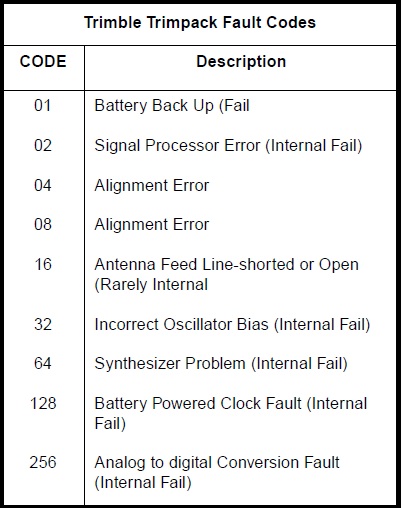
System Test Procedures. Once powered, the system will execute an initial self-test procedure, as well as provide continuous monitoring of key operational parameters. Should a system error be identified, the Trimpack will display a system failure message and diagnostic data in the form of an error code. Applicable codes are described in Figure 1-11-22. The test sequence detects 90 per cent of all major failures and has no more than a 5 per cent false alarm rate.