The transmitter-receiver (Figure 1-11-6) provides generation of RF power for transmission at a fixed frequency of 9.375 gigahertz and reception of returned RF signals for processing and conversion to video signals.
A waveguide assembly is used to feed both RF power from the transmitter to the antenna and received signals from the antenna to the receiver.
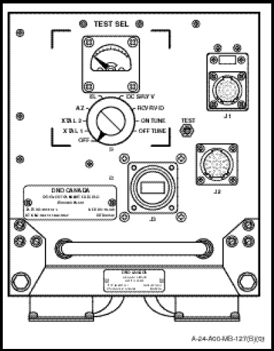
Mounted on the front panel of the transmitter receiver are two switches and a meter which enable fault isolation and monitoring of key radar parameters to be carried out. The controls and their functions are as follows:
a. The TEST SEL control is a nine-position rotary switch used in conjunction with the meter to monitor various circuits. All meter readings should read mid-scale except RCVR VID which will be at or near full deflection. The following functions are provided;
(1) OFF. In this position the meter circuit is checked. The meter should read approximately mid-scale for this and the remaining switch positions, except RCVR VID which should read full scale.
(2) XTAL 1 and XTAL 2. In these positions the respective signal crystal currents are monitored.
(3) AZ. In this position antenna rotation is verified.
(4) EL. In this position the status of the elevation servo loop is verified.
(5) DC SPLY V. In this position the majority of the low voltages generated by the radar set are monitored.
(6) RCVR VID. In this position the transmitter and receiver operations are verified.
(7) ON TUNE. In this position the Automatic Frequency Control (AFC) circuits are monitored.
(8) OFF TUNE. This position is used in conjunction with the TEST switch to monitor the AFC circuits.
b. The TEST control is a spring-loaded pushbutton which is operated in conjunction with the ON TUNE or OFF TUNE position on the TEST SEL switch. It deliberately off tunes the IF frequency causing the AFC circuit to recycle to the required frequency. When the TEST button is depressed the meter should read approximately 10 microamps greater than the meter reading indicated with the switch released.