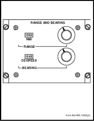
The RANGE AND BEARING control panel (Figure 1-11-4) provides positional control of the bearing cursor and range strobe on the azimuth-range indicator. Two controls and two counters are mounted on the control panel face; their functions are as follows:
a. RANGE. This is a combination of a rotary potentiometer and a three-digit counter. The potentiometer control positions the range strobe on the display in line with the bearing cursor. The range readout is taken from the NMI counter.
b. BEARING. This is a combination of a rotary potentiometer and a three-digit counter. The potentiometer control positions the bearing cursor on the display. The bearing readout is taken from the DEGREES counter.