The MODE 4 function of the radar identification system provides for a secure (encrypted) IFF capability through use of a KIR-1C/TSEC interrogator computer and a KIT-1C/TSEC transponder computer. Together, the KIR-1C and the KIT-1C form the KI-1C crypto computer. With the KI-1C/TSEC operational in the aircraft, the computer processes MODE 4 interrogations and causes the transponder to generate appropriately coded reply signals.
a. The MODE 4 system consists of;
(1) RT862A/APX-77A transponder.
(2) C6280A/APX control.
(3) KI-1C/TSEC crypto computer.
(4) TS1843B/APX in-flight monitor (BITE).
b. The KI-1C crypto computer is located in the aft cabin, right side, upper avionics shelf next to the KY-58. It is electronically coded with the KYK-13 Automatic Transfer Device. For operation, the MODE 4 requires two codes, marked “A” and “B”, to be loaded into the KI-1C. Both codes are loaded simultaneously on a daily basis. The A code is used for today’s period while the B code is used for tomorrow’s period. The only time Code B should be required is when the aircraft is scheduled to fly beyond 2359 Hours ZULU time.
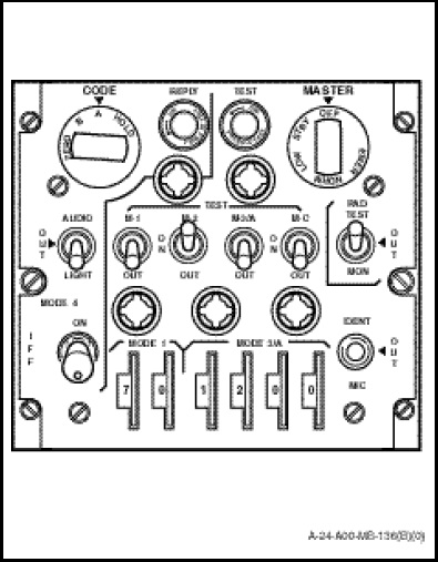
c. The control panel (Figure 1-11-17) is mounted on the radio and navigation control panel between the pilots. The controls and indicator associated exclusively with MODE 4 are grouped in the left and upper portion of the control and segregated with a white dividing line on the control panel face. The functions of the controls are as follows;
(1) The MASTER rotary switch controls transponder operation in MODE 4 as well as in the other modes of operation. MODE 4 will operate normally, when selected, in either the NORM or EMER positions, and at reduced receiver sensitivity in LOW. The MODE 4 function will be inoperative in either STBY or OFF.
(2) With the transponder functioning, MODE 4 operation is selected by placing the MODE 4 ON – OUT toggle switch to ON. Placing the switch to OUT disables MODE 4 operation. Accidental selection of OUT is prevented by the switch design, which requires the operator to pull out on the toggle lever before it can be moved to the OUT position.
(3) The MODE 4 CODE control selects either A or B MODE 4 codes. The HOLD function is not used because the KI-1C is equipped with a battery that enables the system to retain the A and B codes on aircraft shut down.
NOTE
Keying the KI-1C can be accomplished with the power on or off, provided the battery is installed. The equipment can be loaded and operated under aircraft power when no KI-1C battery power is present; however, because the battery is used for code retention, the codes will not be retained when system power is lost.
(4) With aircraft power on and the MASTER switch in any position except OFF, both codes can be zeroized at any time by pulling the MODE 4 CONTROL knob out and turning it to the ZERO position.
(5) When the CODE switch is placed in the A position, the transponder will respond to MODE 4 interrogations from any interrogator using the same code setting. The transponder works in the same manner for interrogations and replies on the B setting.
(6) The AUDIO/OUT/LIGHT switch selects the monitoring method of MODE 4 interrogations. The selections are as follows;
(a) AUDIO. The MODE 4 REPLY light (green) will illuminate each time the system replies to a valid MODE 4 interrogation. If the system fails to reply to a valid MODE 4 interrogation, an audio tone will be heard in the pilots’ head-set and the IFF caution light (amber) will illuminate.
(b) OUT. Both the REPLY light and the audio tone indications are disabled, but the IFF caution light will illuminate if the system fails to reply.
(c) LIGHT. The MODE 4 REPLY light will illuminate each time the system replies to a valid MODE 4 interrogation. The audio tone will be disabled, but the IFF caution light will illuminate if the system fails to reply.
NOTE
The volume of the audio tone can be adjusted with the INTPH-VOL control on the ICS master control panel.