The radar altimeter set provides continuous indication of height (terrain clearance) of the helicopter from 0 to 1000 feet over land and water. During flight above 1000 feet the pointer will mask and the warning flag (black and yellow striped) will appear, even though the system is reliable.
The radar altimeter DC power is protected by a circuit-breaker marked “RADAR HEIGHT” on the DC radio circuit-breaker panel. The AC power is protected by a circuit-breaker marked “RADAR HEIGHT ØB” on the AC circuit-breaker panel.
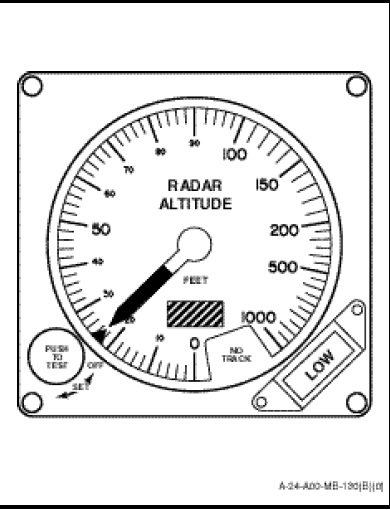
Altitude in feet is shown by two height indicators (Figure 1-11-11) marked “RADAR ALTITUDE” located on the instrument panel in front of the pilot and co-pilot. The indicator consists of a limit control marker (BUG), a low-level warning light and a PUSH TO TEST control knob. The function of controls are as follows:
a. Limit Control Marker (BUG). Adjustable throughout the range of the altimeter by means of rotating the control knob marked “PUSH TO TEST”.
b. Warning Light. A low-level warning light on the lower right corner of the indicator will illuminate and show the marking “LOW” any time the aircraft is at or below the altitude preselected by the BUG.
f. PUSH TO TEST Control. A self-test function is incorporated in the radar altimeter. Depression of PUSH TO TEST control knob on either height indicator at any altitude, providing the coupler mode of ASE is disengaged, will cause a height indication of 100 ±15 feet to be displayed on a serviceable system. Releasing the PUSH TO TEST control knob restores the system to normal operation. The control also serves as a power switch and is the only control necessary for equipment operation.