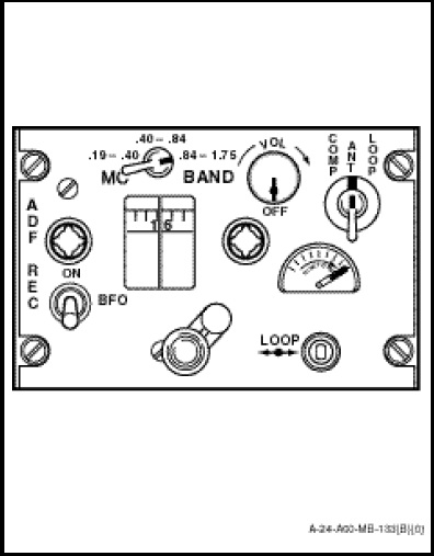
The automatic direction finder control panel (Figure 1-11-14) marked “ADF REC”, is located on the radio and navigation control panel. Controls include a band switch marked “MC BAND”, a volume control marked “VOL – OFF”, a function switch marked “COMP”, “ANT” and “LOOP”, a tuning control, a beat frequency oscillator switch marked “BFO – ON” and a loop switch marked “LOOP”. The function of controls are as follows:
a. The VOL–OFF control turns the set on or off, adjusts receiver audio level when the function switch is in COMP, and adjusts receiver RF sensitivity when the function switch is in ANT or LOOP.
b. The function selector switch is a three-position switch with the following functions;
(1) COMP. With the switch in COMP, the set operates as an automatic direction finder using both the sense and loop antennas. The tuning control may be adjusted to give maximum indication on the tuning meter for any given station and the relative bearing is automatically indicated by the single barred pointer, numbered 1 on the radio magnetic indicator. Relative bearing will also be displayed on pointer No.1 of the pilot’s, co-pilot’s, or TACCO’s BDHI provided that ARN/TAC is selected on the applicable BDHI selector panel.
(2) ANT. With the switch in ANT, the set operates as a communication receiver using the sense antenna only.
(3) LOOP. With the switch in the LOOP position, the set operates as a receiver using the loop antenna.
c. The LOOP switch positions the loop antenna when the function selector switch is in the LOOP position.
d. The BFO–ON switch is used as an aid in the determination of aural nulls on either unmodulated or voice modulated signals. With the BFO switch ON, and the function switch in the LOOP position, the aural tone will rise and fall as the LOOP switch is operated to move the bearing pointer away from or towards the aural null points.
e. The MC BAND selector switch selects the desired frequency range.
f. The tuning crank tunes the receiver to the desired frequency within the selected band.