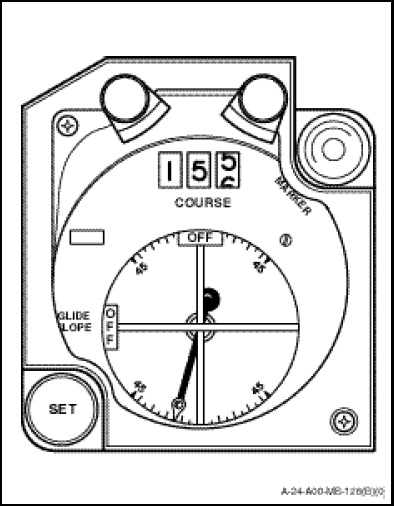
There are two CDIs (Figure 1-11-9) located on the main instrument panel to accommodate VOR or ILS navigation and approach capability from both pilot positions. When TACAN or VOR frequencies are effective, only the vertical bar and rotating pointer are active. The CDI function in these modes is as indicated in paragraph 38.
The marker light located on the top right side of the CDI is functional with the VOR/LOC installed. This green light, when illuminated, indicates which CDI is the command instrument for the mode selected.
When an ILS frequency is selected, the horizontal bar (glide slope) and warning flag are activated if the appropriate NAV switch is activated. The rotating pointer deflection (in ILS mode) is dependent on localizer width.
NOTES
1. ILS approaches flown at NR greater than 103 per cent may produce localizer and glidepath oscillation due to rotor modulation effects on localizer and glidepath antennas.
2. Due to electronic interference, HF radio transmissions may cause deflection of localizer indications when conducting VOR/ILS approaches.
Rotor Modulation is a type of radio interference. Radio signals are attenuated or reflected when the main rotor blades intersect with the radio signal path. This interference with the signal causes a broken or garbled signal to the receiver and is particularly problematic with HF/SSB or VOR/LOC signals.
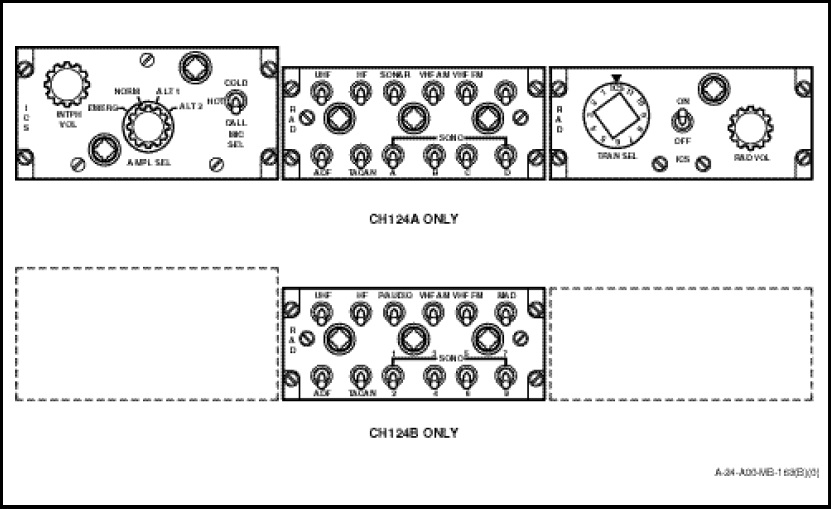
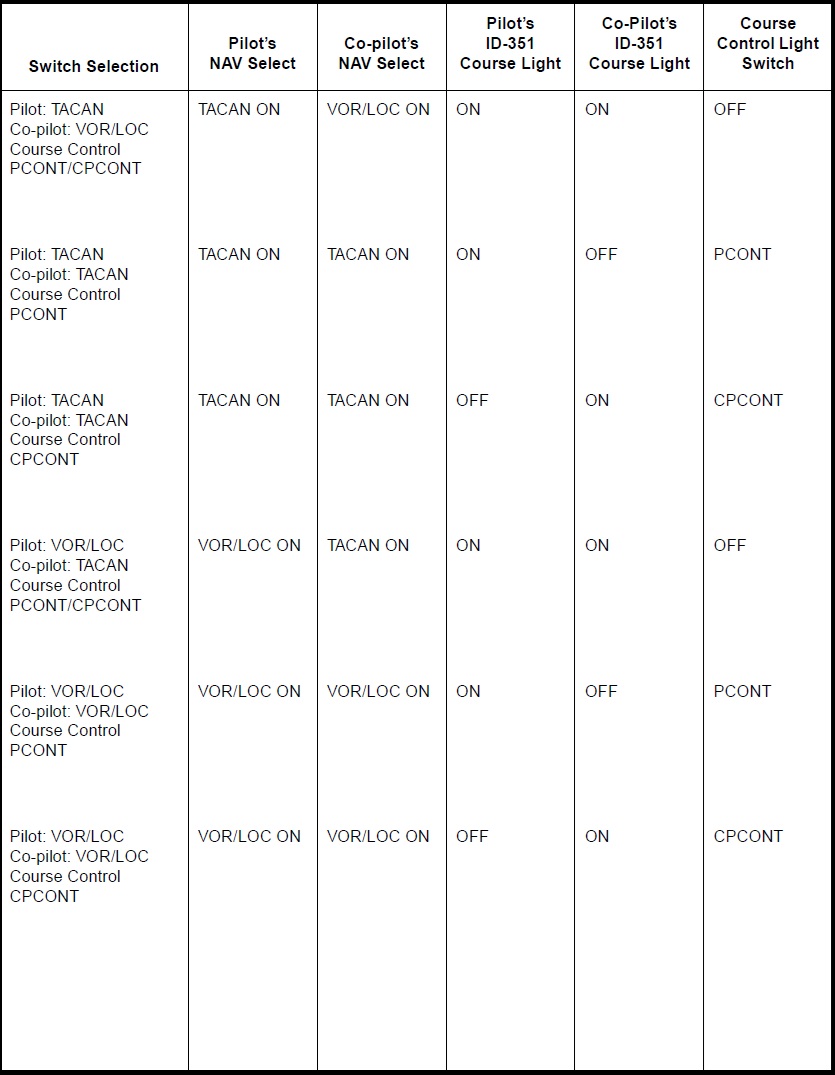
Three NAV select switches (Figure 1-10-7) independently allow the pilot, co-pilot and TACCO to display TACAN or VOR/ILS on their respective Course Indicators and BDHIs (No.2 needle). In VOR/LOC mode, the No.2 needle on the respective BDHI will point to 135 degrees relative if the VOR signal is invalid (weak reception) or if an ILS localizer frequency is selected. The TACAN and ILS audio signals are also switched on by these switches. The TACCO NAV select switch also controls the AESOPs TACAN and VOR/ILS audio. A switching matrix (Figure 1-11-19) is provided to assist in determining information provided through the CDI.