The VHF/FM Saber-1 radio system provides two-way voice communications between the CH124 and an external crew member in the frequency range 148.0 to 174.0 MHz. The system incorporates a duty cycle of 80 per cent standby – 10 per cent listen – 10 per cent transmit.
The complete transportable system consists of seven components housed within a ruggedized protective case. The components include: the Saber-1 transceiver processor unit (with antenna); a rechargeable Ni-Cad battery power supply; a single unit rapid charging unit; a bone conduction ear microphone/speaker attachment; a remote microphone/speaker attachment; an aircrew helmet/Saber-1 radio interface attachment (puck); and a Saber-1 harness assembly.
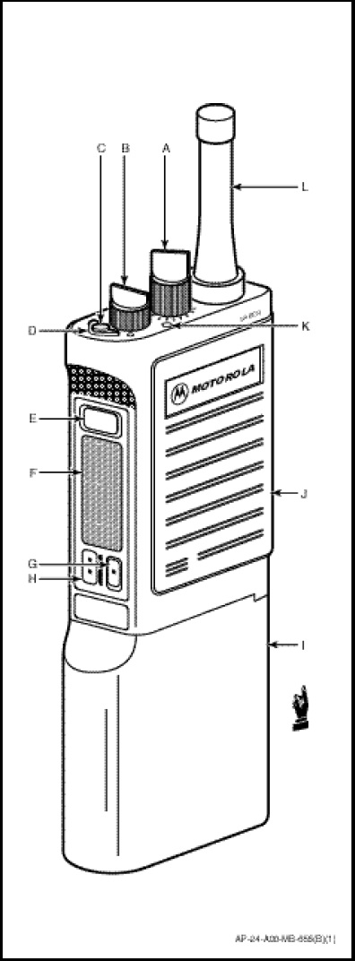
The Saber-1 radio control permits manual selection of any one of 12 pre-programmed channels. The Saber-1 radio system (Figures 1-10-20 and 1-10-21) incorporates the following controls, switches, indicators and connectors:
a. Channel Selector Switch. Selects the transmit and receive frequencies and any operating parameters slaved to each channel position.
b. On/Off/Volume Control. Turns the radio on/off and adjusts audio output level.
c. Emergency Button. Transmits a preprogrammed 2 to 7 tone digital code, followed by a predefined emergency tone. Transmission of this emergency tone can be automatically steered to a pre-programmed channel.
d. Coded/Clear Selector Switch. Coded/clear switch selects clear or coded (digitallyencrypted) voice transmissions. CH124 hoisting Communications Sabers are fitted for but not with the coded communication capability.
e. Monitor Button. Tap to momentarily monitor a channel for voice communications. Press and hold to put the radio into either the carrier squelch (silent monitor) mode or the continuous open squelch (monitor) mode.
f. PTT Switch. Pressing the Press-To-Talk (PTT) switch causes the radio the transmit. It also resets the radio’s alert tones and automatically transmits any tone sequences programmed to the PTT button (for example, unit ID). The receiver operates when the PTT switch is released.
g. Repeater Access 1 Button (<). When this button is pressed, any tone signalling sequence(s) assigned to it will be transmitted. Releasing the button puts the radio in the receive mode. CH124 hoisting Communications Sabers are not repeater capable.
h. Repeater Access 2 Button (:). When this button is pressed, any tone signalling sequence(s) assigned to it will be transmitted. Releasing the button returns the radio in the receive mode. CH124 hoisting Communications Saber radios are not repeater capable.
i. Power Supply. Ruggedized rechargeable Ni-Cad battery.
j. Speaker/Microphone Grill.
k. Multi-function LED. Indicates normal transmission (continuous red in transmit), low battery (blinking red in transmit).
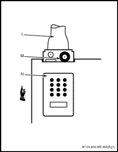
l. Antenna. Heliflex with threaded base.
m. RF Connector. Allows connection of an external antenna or radio test equipment.
n. Universal Connector. Provides access to the radio for programming and testing. Also allows for connection to remote accessories, such as a speaker/microphone. The universal connector has a protective cover which should be left in place when the connector is not in use.
The Saber-1 radio has the following physical and operational characteristics:
a. Weight. 795 grams.
b. Length. 40 centimetres (with antenna).
c. Power Output. 6.0 watts (maximum).
d. Power Supply. Rechargeable Nickel-Cadmium Battery.
e. Channels. 12 (preset).
f. Saber-1 system operator interface attachments;
(1) Bone conduction ear microphone and speaker attachment.
(2) Remote speaker microphone attachment.
(3) SPH5CF aircrew helmet/Saber-1 interface unit (puck).
g. Saber-1 Radio Housing Design. Water resistant and ruggedized.
h. Frequency Band. 148.0 to 174.0 MHz.
i. Range/Altitude Considerations. The range of the Saber-1 is comparable to current CH124 VHF/FM, VHF/AM or UHF radio fit. No definitive range/altitude is available, but is calculated to be line of sight.
Designated frequencies are pre-programmed into each Saber-1 radio for either east or west coast operations. Each frequency is slaved to a Channel Selector Switch position (PX) and are as follows;