The KY-75 secure voice system provides the aircraft with speech security equipment for cipher and plain language operation for the HF radio. The system consists of a signal processor and a control panel used in conjunction with the HF and ICS systems. The KY-75 is capable of storing up to three crypto variable codes for secured voice operation.
Electrical power of 28 VDC for the KY-75 secure voice system is obtained from the DC primary bus through a circuit-breaker on the radio circuit breaker panel marked “KY-75”.
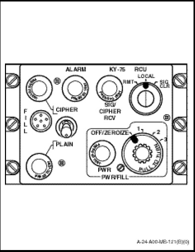
The remote control unit (Figure 1-10-19) is installed on the centre of the TACCO/Sonar Operator station and contains all the operating controls for the KY-75. The switches and their functions are as follows:
a. PWR/FILL Switch. When selected to position 1, 2 or 3 applies power to the secure voice signal processor and also selects the desired register. In the OFF/ZEROIZE position, the power is removed from the processor and all codes stored in the processor are destroyed.
NOTE
If primary power is lost and the PWR/FILL switch is in positions 1, 2 or 3, standby batteries in the processor will maintain the stored key fill information.
b. PLAIN/CIPHER Switch. In the PLAIN position the KY-75 will receive and transmit uncoded or plain text messages. If the switch is in CIPHER position all HF transmissions will be coded and received messages will be decoded providing that the proper fill register is selected.
c. RMT, LOCAL, SIG CLR Switch. RMT position of this switch is not used. In the LOCAL position the transmit mode is controlled by the PLAIN/CIPHER switch. The SIG CLR position is spring loaded to return to the LOCAL position. With no key fill device connected and SIG CLR selected, the unit generates a transmission which signals all units on the net that the operator desires to establish communication on the line. If a key fill device is connected, the selected fill register is cleared and ready to accept a new key upon release of the SIG CLR switch.
The remote control contains five indicator lights and their function is as follows:
a. PWR Indicator. A white indicator which illuminates when power is applied to the signal processor and the PWR/FILL switch is in position 1, 2 or 3.
b. ALARM Indicator. An amber indicator which illuminates when a fill error, randomizer or internal battery failure occurs.
c. CIPHER Indicator. A green indicator which illuminates and remains lit when the CIPHER/PLAIN toggle switch is selected to CIPHER.
d. PLAIN Indicator. An amber indicator which illuminates and remains lit when the CIPHER/PLAIN toggle switch is selected to PLAIN.
e. SIG/CIPHER RCV Indicator. A blue indicator which blinks continuously if the processor is in cipher mode and no signal is being received. When the processor receives a crypto-coded message, the light remains “ON” steady. The light flashes once when intransmit mode with the PTT switch depressed.
NOTE
When the TSEC/KY-75 signal processor is removed from the aircraft, P1 and P2 shall be connected to the two multisocket connectors mounted on the bracket assembly adjacent to the signal processor rack. This completes the circuits for normal operation of the HF communication equipment.