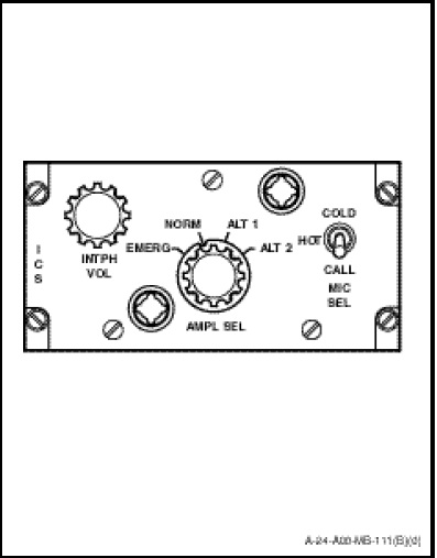
Each crew station has an ICS master control panel which contains isolation and microphone amplifiers and is the master control for the interphone radio system at each station. The panel marked ICS (Figure 1-10-1) consists of an amplifier selector switch marked AMPL SEL, a microphone selector switch marked MIC SEL and an ICS volume control knob marked INTPH VOL. The function of the switch and controls are as follows:
a. The AMP SEL switch is a four-position rotary type with positions marked “EMERG”, “NORM”, “ALT 1” and “ALT 2” with the following functions;\
(1) EMERG Position. Provided so that in the event of failure both the isolation and microphone amplifiers, or a failure of the ICS power, UHF and HF radio communication is possible and intercom is possible by utilizing the radio side tone on UHF or HF. The appropriate selections for UHF or HF shall be made on the transmitter selector and receiver selector panels and the appropriate radio shall be on and functioning. Neither the radio nor the ICS transmission switches shall be made to utilize the radio side tone.
NOTES
- The radio side tone communication may be very weak. As the EMERG position does not allow ICS communication using the ICS transmission switches or the HOT MIC selection, it may be necessary to transmit on the selected radio, using the radio transmission switch, to establish clear internal communications.
- The hoist operator position is not provided with either a transmitter selector panel or a radio transmission switch, and therefore cannot communicate to other stations when EMERG is selected. The hoist operator station can monitor other stations when EMERG is selected by selecting the appropriate receiver on the receiver selector panel.
(2) NORM Position. Provided for normal intercommunications in the aircraft. All incoming radio and ICS signals pass through the isolation amplifier to the head-set and all microphone audio passes through the microphone amplifier.
(3) ALT 1 Position. Both audio and microphone signals pass through the isolation amplifier.
(4) ALT 2 Position. Both audio and microphone signals pass through the microphone amplifier.
NOTE
This enables a station with a faulty isolation or microphone amplifier to select ALT 1 or ALT 2 respectively and maintain normal ICS.
b. The MIC SEL switch has three positions, COLD, HOT and CALL with the following functions;
(1) COLD. Normally used and requires the use of the microphone switch.
(2) HOT. Gives continuous open microphone.
(3) CALL. A spring-loaded override position which allows ICS to all stations regardless of their switch positions and overrides the SENSO/sonar operator’s SONAR DIRECT mode.