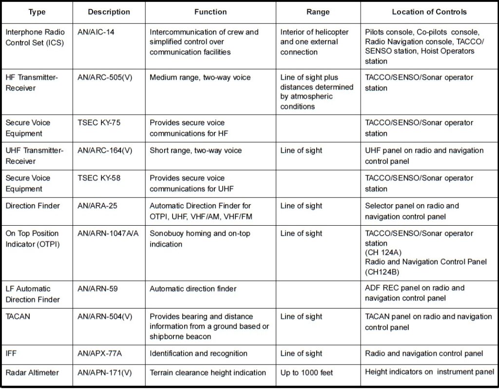
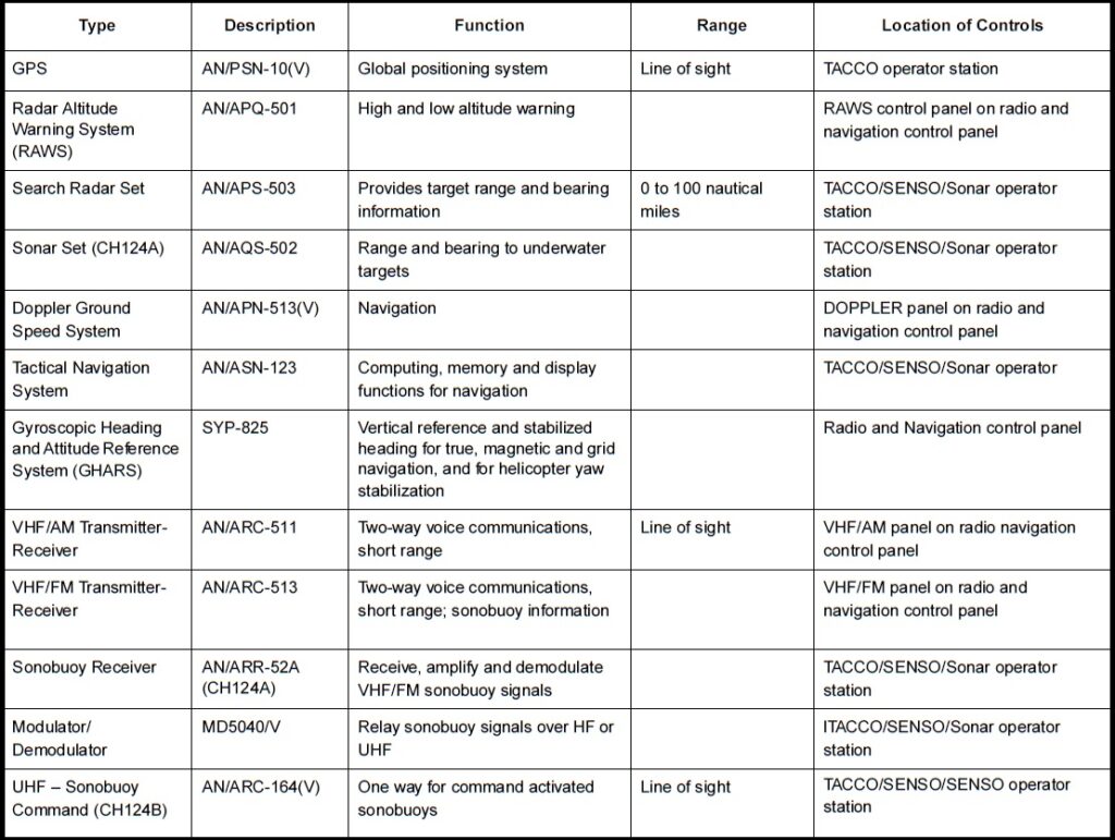
The communication, navigation, and associated electronic equipment installed in the helicopter is listed in Figure 1-9-4. The equipment is protected by circuit-breakers on the overhead circuit breaker panel, the AC circuit-breaker panel and the radio circuit-breaker panel (Figures 1-5-5 and 1-5-6).
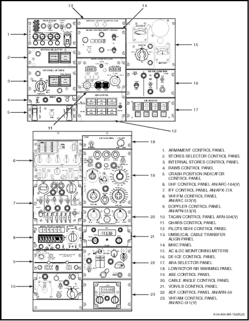
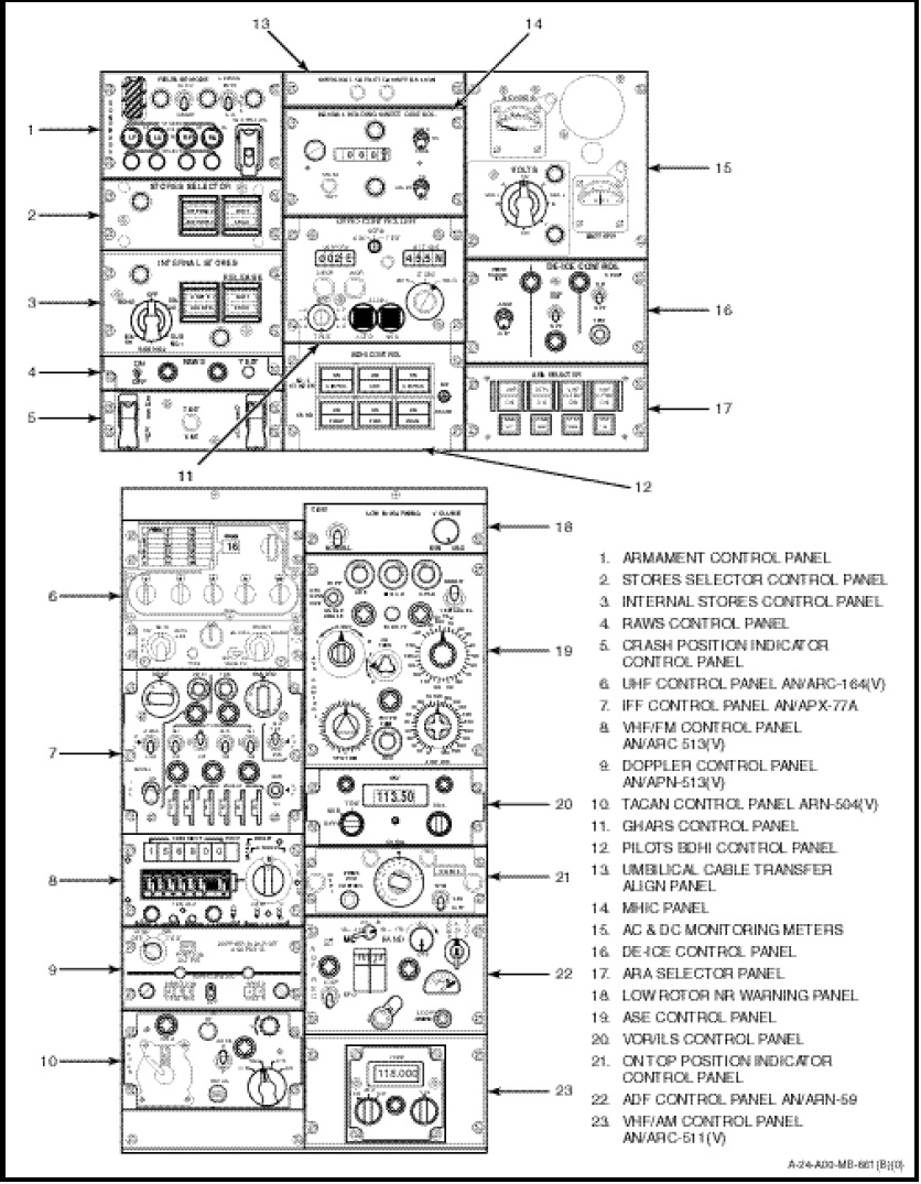
Control over the 28 VDC power supply is provided by RADIO MASTER switches, located on the overhead switch panel (Figure 1-2-9). Operating controls for all the equipment are located on the radio and navigation control panel (Figures 1-9-2 and 1-9-3), the pilot’s console (Figure 1-10-8), the sensor station (Figure 1-10-9), the co-pilot’s console (Figure
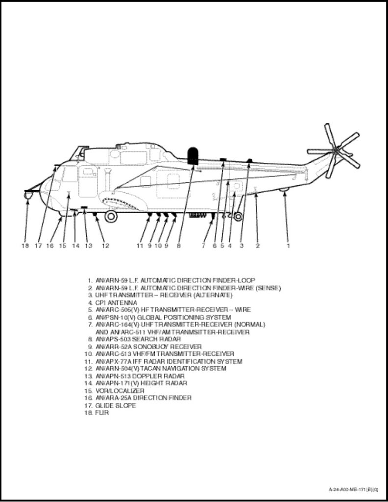
1-10-7) and the hoist operator’s control panel. Indicators used in conjunction with the navigation sets are located on the instrument panel (Figure 1-2-11) and the sensor station. Sonar equipment is located in the cabin. For location of antennas, see Figure 1-9-1.