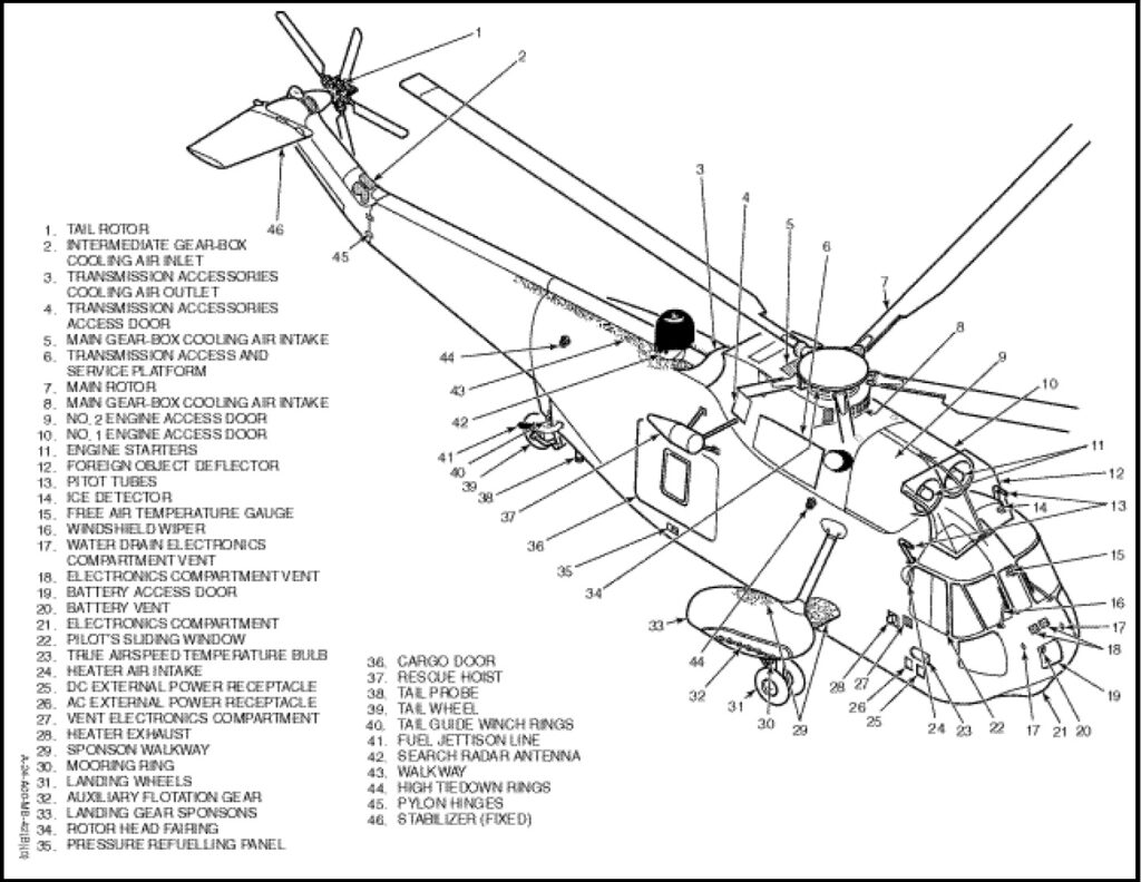
The CH124 is designed as an all-weather ASW helicopter. It is certified for flight under Instrument Flight Conditions. It may be operated from either shore bases or ships. Configuration is a single main rotor, twin gas turbine powered helicopter with emergency amphibious capabilities. Amphibious capability is provided by a boat-type hull bottom and two outrigger sponsons into which dual main landing wheels can retract. A fixed tail wheel is located on the aft end of the hull.
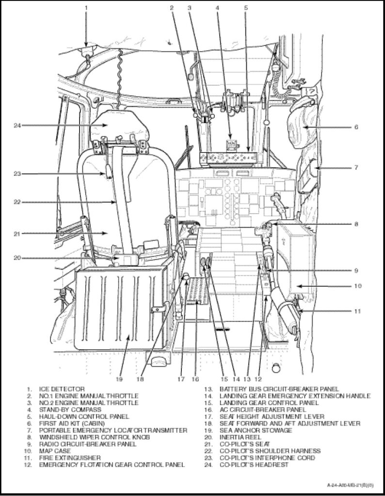
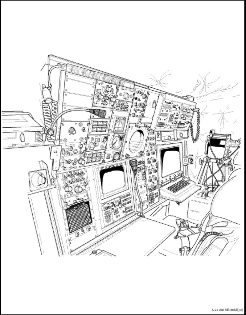
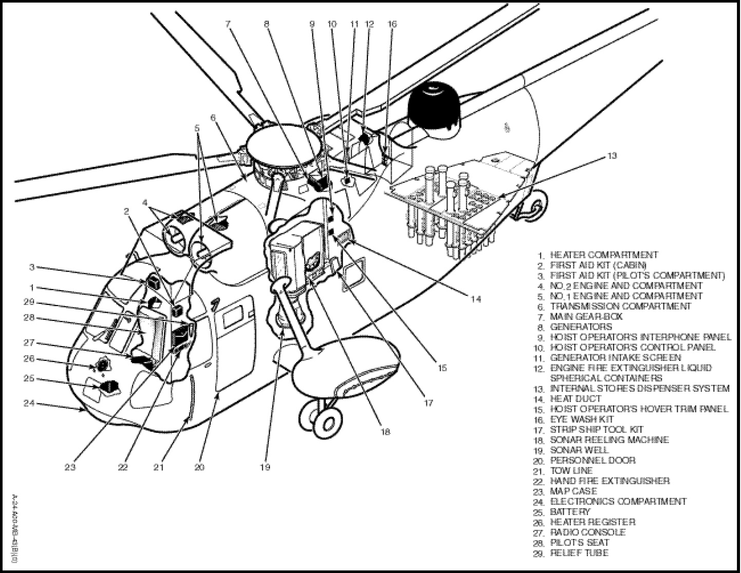
The fuselage (Figures 1-1-1, 1-1-2 and 1-1-3) is all-metal semi-monocoque construction and compromises five sections: the forward fuselage section, the hull, the aft fuselage section, the tail cone section, and the pylon. The forward fuselage section and hull consist of the cockpit (Figures 1-1-4 and 1-1-5), engine compartment, transmission compartment, cabin and fuel tanks.
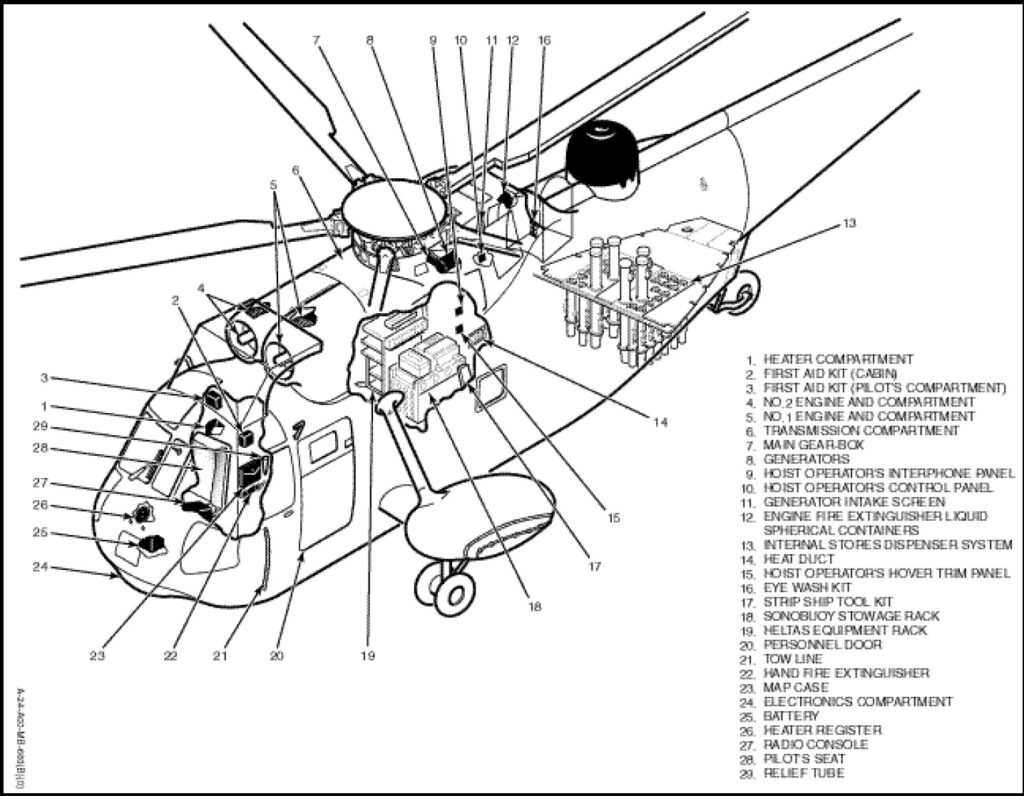
The two gas turbine engines are mounted side-by-side in the engine compartment with the engine shafts directed aft into the main gear-box. Directly aft of the engine compartment is the transmission compartment housing the main gearbox. The main rotor head assembly, to which the five main rotor blades are attached, is splined to the main gear-box drive shaft. Shafting extends aft from the main gear-box lower housing to the intermediate and tail gear-boxes to drive the tail rotor.
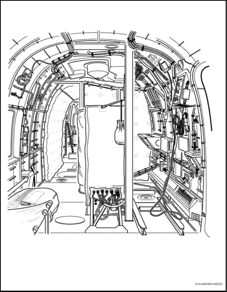
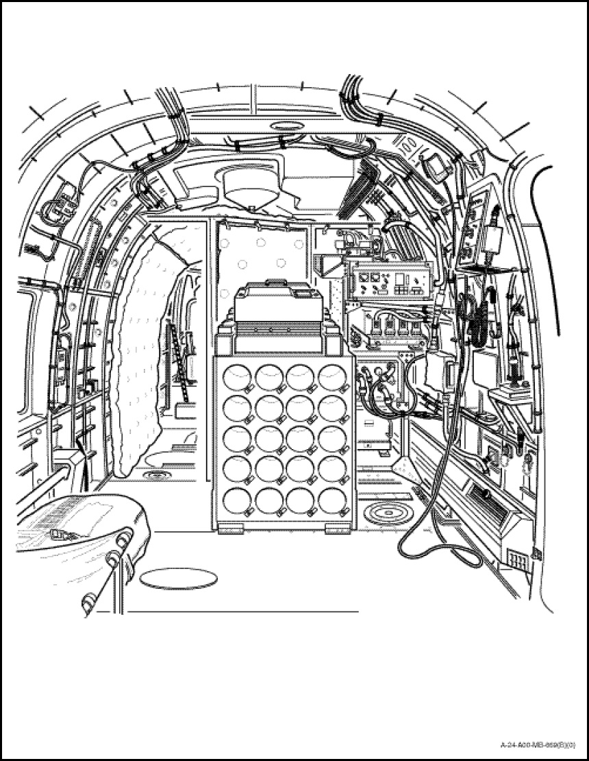
The cabin (Figures 1-1-6, 1-1-7, 1-1-8 and 1-1-9) is located directly below the engine and transmission compartments. It may be entered either through the sliding cargo door on the right-hand aft side of the cabin or through a hinged personnel door on the left-hand side of the cabin. A search radar antenna and radome are mounted directly aft of the main gear-box. In the CH124A a sonar well in the cabin floor is provided for ASW search equipment. Four externally mounted torpedo launchers, two on each side of the fuselage are provided for ASW attack missions. Two multi-cell crash worthy fuel tanks are installed in the hull below the cabin floor.
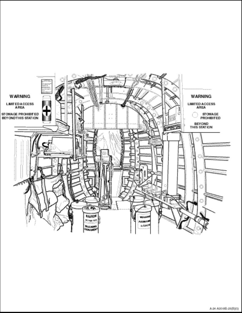
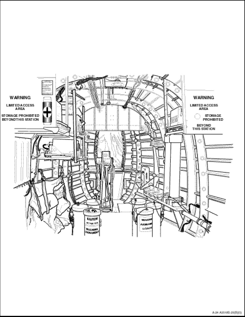
The aft fuselage section (Figure 1-1-10) and the tail cone section extend aft from the rear cabin bulkhead. The aft fuselage section houses radio equipment, search radar receiver-transmitter and the tail probe mounting structure. An internal stores dispenser system is installed in the aft fuselage section floor. The compass magnetic-flux valve, compensator and the CPI battery control-pack are the only pieces of equipment installed in the tail cone section. The tail pylon is attached to the rear of the tail cone. A horizontal stabilizer is installed on the upper right side of the pylon. The intermediate gear-box is installed in the lower portion of the pylon with a shaft extending upward to the tail rotor gear-box at the top of the pylon. The five-bladed tail rotor is splined to the tail rotor gear-box. To facilitate storing, the five main rotor blades may be folded parallel to the fuselage and the pylon may be folded forward along the right hand side of the tail cone using the helicopter utility hydraulic system.
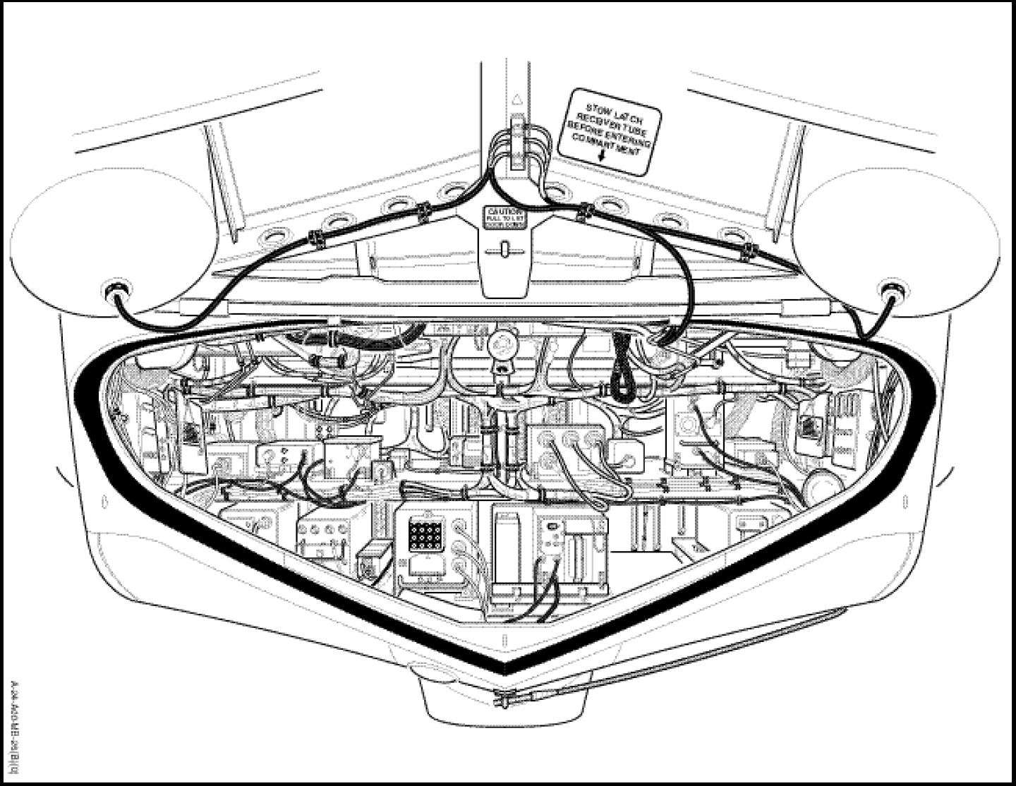
The electronics compartment (Figure 1-1-11) is located in the forward portion of the hull. Above the electronics compartment and forward of the cabin is the cockpit which is entered from the cabin. The engine compartment is located above the forward portion of the cabin.
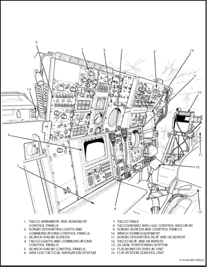
Electronic Systems used on the helicopter are grouped under Radio, Navigation, Anti-Submarine Warfare, Compass and Tactical Navigation.