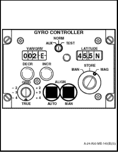
The GYRO CONTROLLER panel (Figure 1-14-16), located on the radio and navigation control panel, provides most of the operating controls for the GHARS. The functions of the operating controls and indicators are as follows:
a. AUX/NORM/TEST. A three-position switch, which selects the vertical mode of operation for the system. NORM and AUX positions are used while airborne; the only difference being the erection rate of the vertical gyro. NORM provides a vertical gyro erection rate of 30 degrees per hour. However, if the vertical gyro continues to process off the vertical, the AUX position may be selected, giving an erection rate of 60 degrees per hour. TEST position is for ground use only, used to test GHARS ability to maintain a dynamic verticality of ±1.5 degrees.
b. GRID/TRUE. A twelve-position, rotary type switch, which selects the desired operational heading mode. When selected to TRUE, the system compensates for earth’s rate and meridian convergency. When selected to GRID, the system compensates for earth’s rate. The numerical markings on the switch are used when operating in the grid mode to set in RTW corrections.
c. MAN/STORE/MAG. A three-position switch used to select the desired alignment mode. When selected to MAN, the system aligns to a manually selected heading on the MHIC panel. When selected to STORE, the system aligns to a heading previously stored in the CRA-3 and, when selected to MAG, the system aligns to true or grid north, using the magnetic flux valve as a reference and adding controller variation.
d. LATITUDE. An indicating counter and knurled knob which sets sine, cosine and tangent potentiometers within the controller for the correct earth’s rate and convergency correction for the selected latitude. Automatic updating is affected, providing a doppler input is available.
e. VAR/GRIV. An indicating counter which displays the variation/grivation angle, as set by the INCR/DECR push-buttons on the controller.
f. INCR/DECR (Helicopter On Ground). Momentary push-button switches used to set the variation/grivation angle in an E (Easterly) or W (Westerly) sense respectively.
g. INCR/DECR (Helicopter Airborne) Slave Mode. Used as a means of updating the variation in the gyro controller to match the local variation. FREE mode is used to correct gyro drift, torques gyro or true heading up or down scale at a rate of 1.7 degrees per minute. VAR/GRIV counters will be driven in an easterly or westerly direction as appropriate.
h. AUTO ALIGN. A push-button switch and integral indicator light which, when depressed, commands alignment of the GRU to the reference selected on the MAN/STORE/MAG switch. The light on the switch remains illuminated and alignments perform for 60 ±5 seconds when power is initially applied to GHARS and subsequently for 30 ±5 seconds when this selection is made.
i. MAN ALIGN. The MAN ALIGN button operates in the same manner as the AUTO ALIGN with the exception that alignment occurs only while the button is held depressed. Release of the button causes the integral light to extinguish and the alignment cycle to be de-energized.