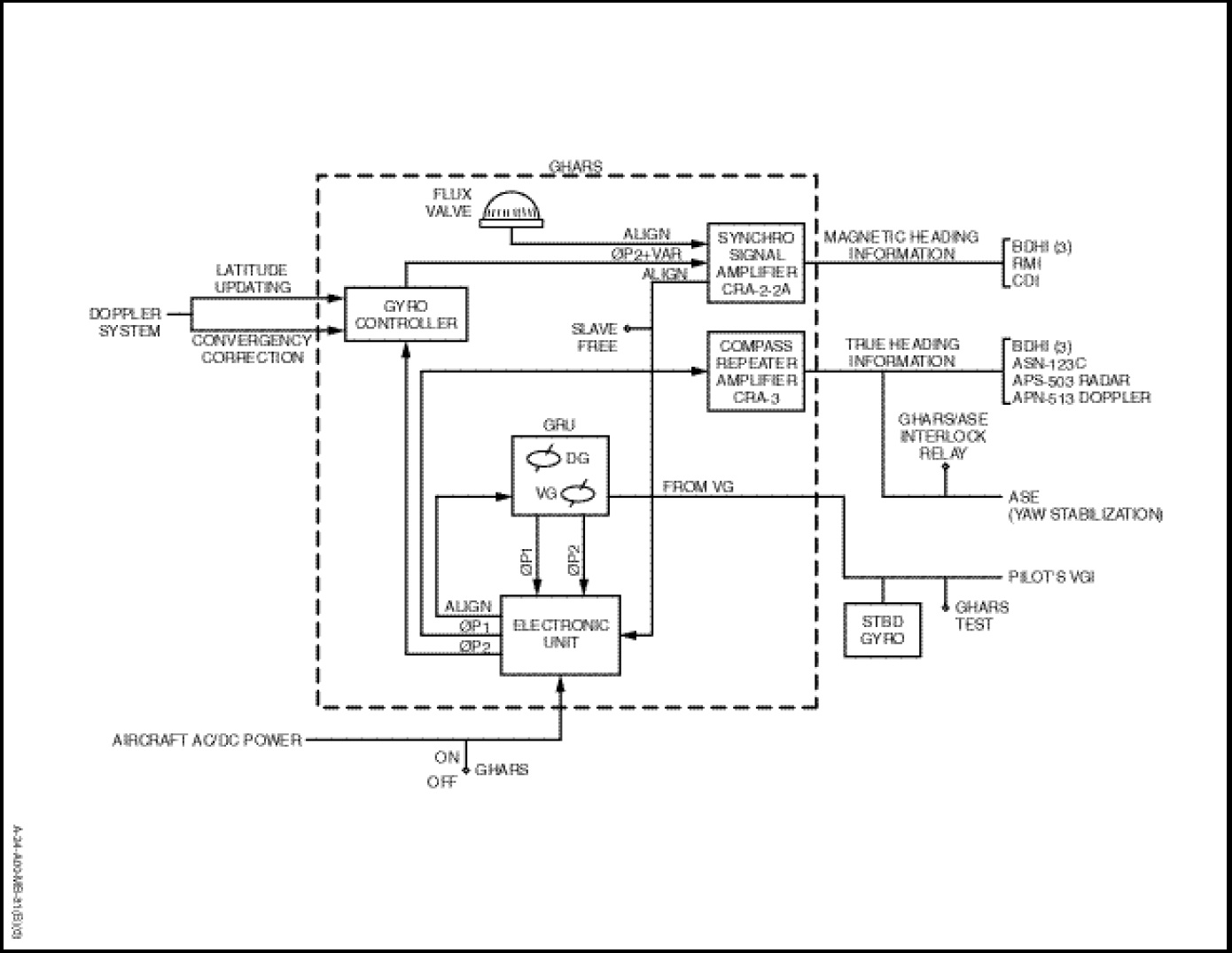
The gyroscopic heading and attitudereference system (Figure 1-14-14) provides an accurate, reliable, inertially stabilized heading and vertical reference for true and grid navigation and for helicopter yaw stabilization. A GHARS/ASW interlock automatically disconnects the heading reference from the ASE yaw channel during GHARS alignment cycles. The system requires analog and digital input data from the doppler system and input from the azimuth magnetic detector (flux valve).
The GHARS is capable of furnishing continuous angular pitch, roll and azimuth information. The effects of meridian convergency, Residual Transport Wander (RTW) and earth’s rate are compensated for within the system.
The system is capable of operating over the entire surface of the earth in the grid mode and up to ±70 degrees latitude in the true mode. Longitudinal and lateral helicopter acceleration or deceleration in excess of 0.23 G, which affects the verticality of the platform, is monitored and compensated for within the gyro reference unit.
When the helicopter is shipborne, a provision is available which enables initial alignment for the GHARS to be obtained from the ships gyro. This is achieved by the transfer of the signal from the ships gyro to the helicopter via an umbilical cable. Connection of the cable to the helicopter is by a weatherproof, recessed connector located adjacent to the ground intercom connector. Two indicator lights on the radio and navigation control panel provide indication of the following functions:
a. An UMBILICAL CABLE light illuminates when the umbilical cable is connected to the helicopter.
b. A TRANSFER ALIGN light illuminates when the GHARS has received the signal from the ships gyro.
A capsule (GHARS) on the caution panel illuminates when system power is lost. The system is protected by one DC circuit-breaker, marked “GHARS”, on the overhead circuit-breaker panel and three AC circuit-breakers, marked “GHARS”, on the AC circuit-breaker panel. The system receives DC power from the essential bus and AC power from the No.1 generator.
