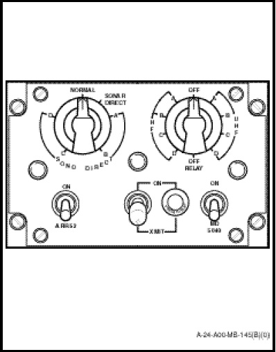
The control panel (Figure 1-12-13) located on the SENSO/Sonar operator station, above the frequency indicators provide the operator with controls necessary to apply power to the system and to interface with ICS, HF and UHF systems. The panel contains two rotary switches, three toggle switches, and a press to test type indicator lamp. The function of switches and controls are as follows:
a. The ARR 52 ON power switch supplies power for the sonobuoy receivers.
b. MD 5040 ON power switch supplies power for the modulator-demodulator.
c. XMIT switch selects transmission via the HF or UHF radios.
d. The indicator lamps indicate data transmission.
e. RELAY/OFF/HF/UHF rotary switch selects sonobuoy receiver A, B, C, D for data transmission on either UHF or HF radios.
f. NORMAL/SONAR DIRECT/SONO DIRECT rotary switch selects normal intercom facilities, sonar direct or sono direct channels A, B, C or D.