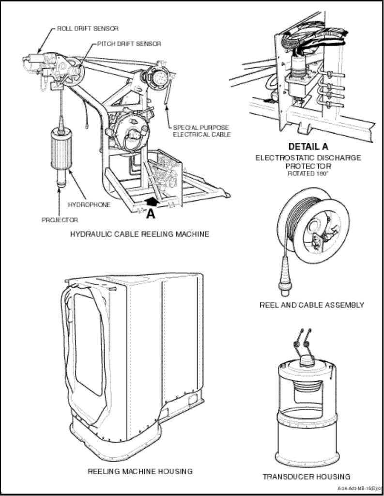
The hydraulic cable reeling machine (Figure 1-12-8) is employed to lower and raise the sonar transducer using a hydraulic motor powered by the utility hydraulic system. The sequence of raising or lowering is accomplished by energizing solenoids, on a hydraulic control package, which programmes hydraulic pressure to release or retrieve the transducer. When the LOWER switch on the dome control is depressed, the reeling machine lowers the transducer at rates of 8 feet per second in air and 3 feet per second in water. The restricted free fall is accomplished by reducing the return rate of hydraulic fluid by means of an orifice. Limit switches prevent the reeling machine from paying out the entire length of cable, and sequence the trail and seating functions when the cable is retrieved. When approximately four turns of cable are left on the drum, the lower limit switches actuates a hydraulic valve which stops the flow of hydraulic fluid through the orifice. If the lower limit switch malfunctions, a backup limit switch will stop the lowering action. The lower limit switches should not be used as a means of stopping the lowering sequence during normal sonar operations.
When the RAISE switch on the dome control is depressed, the transducer and cable are reeled in at a rate of 11 feet per second up to 40 feet of depth, then 5 feet per second to 10 feet below the helicopter and then 1 foot per second to the trail position. When the transducer is 18 ±6 inches below the helicopter, the trail limit switch actuates and stops the raise function. The raise operation is completed by depressing the SEAT push-button on the dome control. The seat limit switch, located on the reeling machine boom, automatically stops the raise sequence when the transducer is properly seated. If this automatic feature fails, a mechanical stop is incorporated in the structure of the hoist to stall either the hydraulic or DC motor.
If the hydraulic motor fails, the DC motor can be used to retrieve the sonar transducer and cable by depressing the AUXILIARY RAISE push-button on the dome control. This motor will retrieve the transducer at a rate of 4 feet per second as long as the AUXILIARY RAISE push-button is depressed or until the motor is stalled by the transducer engaging the mechanical stop on the hoist. The raise cycle shall be stopped if the transducer is seen to be approximately 10 feet below the fuselage. The transducer shall then be brought to the seat position using the hand crank located in the aircraft tool kit. The DC motor and associated circuitry is protected by an 80 ampere current limiter and an 80 ampere circuit-breaker, both located in the electronics compartment.
In the event that both the normal RAISE/LOWER and the AUXILIARY RAISE systems fail, the transducer may be recovered by use of the alternate hydraulics. The alternate hydraulic system consists of three buttons located on the back of the sonar reeling machine near the electrical/hydraulic connections. These buttons are marked “SYSTEM”, “RAISE” and “LOWER”. To raise or lower the transducer using the alternate hydraulic system, the SYSTEM and RAISE or LOWER buttons shall be pressed simultaneously. The alternate hydraulic system will raise the transducer at a rate of 11 feet per second while the SYSTEM and RAISE buttons are depressed. When the transducer is approximately 10 feet below the helicopter the raise will slow to 1 foot per second as a result of a mechanical (flow actuating) cam in the hydraulic system. The system may switch to 5 feet per second when the transducer reaches a depth of 40 feet depending on the serviceability of the sonar depth pot. Because of the speed of the raise cycle, coupled with delay in the hydraulic system to react to the release of the SYSTEM and RAISE buttons, the raise sequence should be stopped when the transducer visually clears the water. This should result in the transducer stopping approximately 10 feet below the helicopter. The transducer may then be beeped to the trail position and an attempt made to seat the transducer by depressing the SEAT button. If unable, the transducer shall then be seated by using the hand crank located in the aircraft tool kit.
Drift-sensing assemblies provide longitudinal and lateral drift information from precision sensors to the Automatic Stabilizing Equipment (ASE) and hover indicator, and a cable payout potentiometer electrically monitors the amount of special cable payed out when the transducer is lowered. The voltage at the arm of the potentiometer is used in conjunction with transducer depth voltage to determine aircraft height.