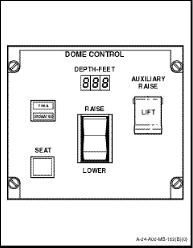
The dome control (Figure 1-12-7), mounted on the SENSO/Sonar Operator station above the azimuth and range indicator, provides for control of the hydraulic cable reeling machine in the lowering and raising of the special purpose cable and transducer assembly. Logic circuits contained in the dome control detect and activate the fault indications should an open or short circuited depth or cable payout potentiometer occur; or the helicopter descend to less than 20 +10 feet; or if the rate of change in height exceeds approximately 5 feet per second after transducer water entry. The control and indicator functions are as follows:
a. DEPTH-FEET Indicator. Displays transducer depth in feet whenever the transducer is submerged to a depth equal to or greater than 8 feet. A SONAR SUB lamp on the advisory panel illuminates when the transducer reaches a depth of 10 feet.
b. TRAIL/UNSEATED Indicator. Advises the operator of the transducer position. TRAIL capsule illuminates amber when transducer is in the trail position. The UNSEATED capsule illuminates red when the transducer is not in the seat position.
c. SEAT Indicator/Push-button Switch. Used for raising the transducer from the trail position. When depressed, applies 28 VDC to reeling machine solenoids to activate transducer seat operation and is operational only when both TRAIL and UNSEATED indicators are illuminated. The TRAIL indicator extinguishes when SEAT switch is depressed. The SEAT indicator/push-button switch illuminates green when transducer is in seat position and switch is depressed.
d. RAISE/LOWER Switch. For energizing the reeling machine hydraulic raise or lower sequence. When the upper portion is depressed, 28 VDC is applied to reeling machine solenoids to raise the transducer whenever the transducer is below the trail position. When the lower portion is depressed, 28 VDC is applied to the reeling machine solenoids to lower the transducer.
e. AUXILIARY RAISE Indicator/Push-button Switch. Operates DC motor to raise the transducer in the event of a malfunction of the dome control RAISE/LOWER switch or hydraulic motor. The switch is guarded by a cover marked “LIFT”. The button is marked “PUSH” and is illuminated red when not in use. The PUSH button illuminates amber when depressed.