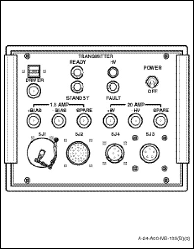
The sonar transmitter (Figure 1-12-4) mounted on the SENSO/Sonar Operator station adjacent to the sonar receiver, produces a 3.5 millisecond pulse or a 35 millisecond pulse in SHORT or LONG pulse mode, for echo-ranging operations and transmits audio in the COMM mode. The front panel contains a switch, indicators, fuses, electrical connectors and cover plate. The control and indicator functions are as follows:
a. POWER Switch. When selected to on applies 115 VAC three phase power to the transmitter. When selected to OFF removes the 115 VAC three phase from the transmitter.
b. Time Meter. Presents a digital display of the accumulated hours the transmitter has been in operation.
c. HV (High Voltage) Indicator. The yellow HV indicator, when illuminated, indicates presence of +160 volts and –160 volts.
d. READY Indicator. The green READY indicator, when illuminated, signals the transmitter is ready for operation and the following conditions are satisfied;
(1) A 35 second delay has elapsed.
(2) Temperature sensors are operational.
(3) Temperature is nominal.
(4) +80 volt and +160 volt circuits are operational.
(5) –80 volt and –160 volt circuits are operational.
(6) Three phase input power is present and proper level.
(7) Delay cycle of output is nominal.
e. STANDBY Indicator. The blue STANDBY indicator, when illuminated, signals one of the following conditions;
(1) A three phase input voltage is not present.
(2) A three phase input voltage level is too low or too high.
(3) Duty cycle of output is out of tolerance.
f. FAULT Indicator. The red FAULT indicator, when illuminated, indicates that one of the following malfunctions has occurred;
(1) A three phase input voltage level is too low or too high.
(2) Duty cycle of output is out of tolerance.
(3) Output power level is out of tolerance.
(4) Temperature sensor is faulty.
(5) Temperature range is exceeded.
(6) +80 volt or +160 volt circuits are faulty.
(7) Blown fuse.
g. Fuses. A 1.5 amp fuse is provided for DRIVER, +BIAS, –BIAS and SPARE. A 20 amp fuse is provided for +HV, –HV and SPARE.