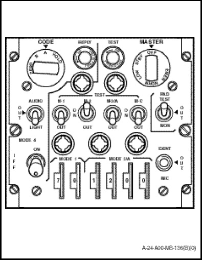
The transponder control panel (Figure 1-11-17) marked “IFF” is located on the radio and navigation control panel and contains all the operating controls except for MODE 2 settings which are located on the receiver-transmitter in the electronics compartment.
a. The MASTER switch selects five conditions of operation;
(1) OFF. Power is not applied to the system components.
(2) STBY. Power is applied to the system, the receiver-transmitter is warmed up ready to respond, but no signals will be transmitted.
(3) LOW. Receiver sensitivity is reduced by a preset amount such that only higher energy signals will trigger the receivertransmitter.
(4) NORM. The receiver-transmitter will operate at normal sensitivity and respond to interrogations In Accordance With (IAW) settings of other controls.
(5) EMER. Emergency signal responses will be transmitted in MODES 1, 2, and 3/A regardless of the settings of the mode control toggle switches. To prevent accidentally switching to the emergency (EMER) or the OFF position, the switch knob shall be pulled out before the switch can be turned to either of these positions.
b. There are four MODE enabling toggle switches identified as “M-1”, “M-2”, “M-3/A” and “M-C”. Each switch has two marked positions “OUT – ON”, with common marked “TEST” positions for all four switches in the up position. The four switches are spring loaded against the up position;
(1) OUT. Position prevents responses in each MODE.
(2) ON. Position permits responses in each MODE.
(3) TEST. Position will illuminate the press to test TEST light, in the upper section of the control panel if the transponder is replying. This feature is only functional when the MASTER switch is in NORMAL.
NOTE
The green TEST light may illuminate when the MASTER switch is in STBY and each mode switch is set to TEST however the system is not testing.
c. The code setting dials make the desired mode setting.
(1) The two numeral wheels on the left marked “MODE 1” are for setting the desired MODE 1 code. The code is selectable from 00 through 73.
(2) The four numeral wheels on the right marked “MODE 3/A” make the MODE 3/A settings. The code is selectable from 0000 through 7777. On the right side of each numeral window, along the lower edge of the control panel is a protruding blunted spike. Light finger pressure on the spikes, either up or down, will rotate the numeral wheels.
d. The toggle switch marked “IDENT”, “OUT”, and “MlC” at the lower right side of the control panel provides the following functions;
(1) In the momentary IDENT position, approximately 20 seconds of identification signals is provided on modes 1, 2, or 3/A. A spring load will return the switch to OUT or centre position.
(2) In the MIC position, approximately 20 seconds of identification signals is provided on modes 1, 2, or 3/A, each time a microphone switch is depressed to the radio position.
(3) No identification will be made in the OUT position.
e. The RAD-TEST, OUT, MON toggle switch on the right centre of the control panel provides the following functions;
(1) TEST. Test position is used for maintenance testing only.
(2) OUT. Position disables the switch
(3) MON. Position enables monitoring of receiver-transmitter replies to external interrogations. The TEST light will illuminate to indicate that the transponder is replying.
The MODE 2 code settings shall be made on the receiver-transmitter front panel in the electronics compartment. Four numeral windows, marked “MODE 2”, display the selected code. Light finger pressure either up or down on the blunted spikes at the right of each numeral will rotate the numeral wheels. MODE 2 selects a desired code from 0000 through 7777.
NOTE
The receiver-transmitter is located in the electronics compartment; therefore MODE 2 settings shall be made before flight.
The IFF receiver-transmitter is powered by the essential DC bus and is protected by two 5 ampere circuit-breakers, marked “IFF”, in the DC section of the radio circuit-breaker panel. The KIT-1C/TSEC computer transponder is powered by the AC power supply systems from the No.1 generator. The circuit is protected by a 5 ampere circuit-breaker, marked “IFF”, on the radio circuit-breaker panel (Figures 1-5-5 and 1-5-6).