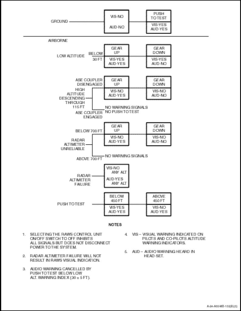
The radar altitude warning system provides the pilot and co-pilot with visual and/or audio warning signals for the following unsafe conditions:
a. The aircraft flies below 115 feet with the landing gear up. This function is disabled if the ASE coupler is engaged.
b. The aircraft flies below 30 +5 feet with the landing gear up.
c. A power failure within the radar altimeter system.
d. The radar altimeter system becomes unreliable below 700 +50 feet.
The RAWS is protected by one AC circuitbreaker on the AC circuit-breaker panel and one DC circuit-breaker on the overhead circuit-breaker panel. Both circuit-breakers are marked “RAWS”. The system receives DC power from the primary bus, and AC power from the No.1 generator.
The RAWS consists of an alarm unit, located in the electronics compartment, and a control panel located on the left-hand side of the radio and navigation control panel. The control panel (Figure 1-11-12) consists of a toggle switch and a TEST button. The function of controls are as follows:
a. The ON/OFF toggle switch has the following functions;
(1) ON. Audio and visual warning indications are provided to the pilot and co-pilot.
(2) OFF. System is inhibited and no warning indications are provided.
b. TEST Button. Operation of the spring-loaded TEST button on the ground or below 450 feet enables a check of the visual and audio warning signals to be carried out. Operation above 450 feet will only enable audio warnings.
NOTE
Selecting the RAWS control unit ON/OFF switch to OFF inhibits all signals but does not disconnect power to the system.
The take-off barometric pressure is automatically referenced during the first second after application of DC power. If at any time the DC power is interrupted to the RAWS, the system will re-reference to the barometric pressure existing when power is interrupted. This would alter the audible warning of below 700 +50 feet above a take-off altitude. Operation of the RAWS power switch will not cause a re-reference of barometric altitude.
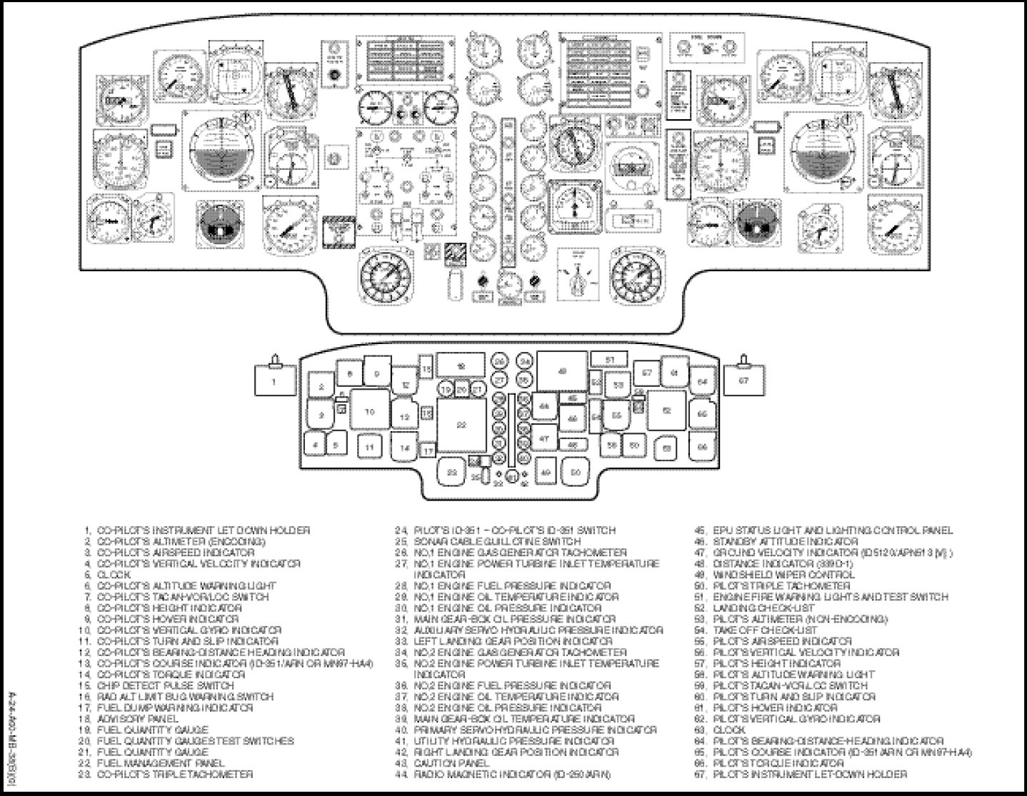
Two ALTITUDE lights on the instrument panel, one at the pilot’s and one at the co-pilot’s station (Figure 1-2-11) provide visual indications of warning signals. The audio warning signals are routed via the communication system to the pilot’s and co-pilot’s head-sets and their volume level is controllable only by the set volume control on the alarm unit. Visual and audio warning signals are triggered under the conditions shown in Figure 1-11-13.