The airborne radio navigation system, TACAN, is used in conjunction with a ground or shipboard UHF omni-directional beacon, providing azimuth information in degrees magnetic or true and slant range distance information in nautical miles. In addition, the airborne set has the capability of measuring range from other aircraft fitted with similar equipment in the Air To Air (A/A) mode of operation. The set also has a Built-In Test (BIT) capability.
When tuned to an appropriate channel, the TACAN receiver continuously receives bearing information as determined by measurement of signals transmitted by the surface beacon.
NOTE
Aircraft memory circuits prevent bearing unlocking due to signal obstruction for 3 to 5 seconds.
Electrical power is supplied by the No.1 generator at 115 VAC and 26 VAC. The 28 VDC is supplied from the No.1 radio bus. The AC power is supplied through the TACAN ØB circuit-breaker on the AC portion of the radio circuit-breaker panel. Also located on this panel is the IND ØB circuit-breaker which supplies a 26 VAC reference signal to the BDHIs RMI, CDI and Distance Indicator. DC power is supplied through the TACAN circuit-breaker on the DC portion of the circuit-breaker panel.
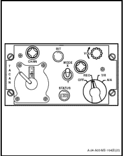
The TACAN navigational set control, marked “TACAN” (Figure 1-11-7) is located on the radio and navigational control panel and contains three control knobs and a mode switch which are used to energize and control the operation of the TACAN equipment. In addition, a test button and status indicator are incorporated for system self-test. The function of controls and switches are as follows:
a. The channel selector marked “CHAN” consists of two concentrically mounted rotary controls providing 126 channel selections, which are read directly from top to bottom on the channel selector. The outer control has 13 positions from a blank to 12 and selects the tens digits. The inner control has 10 positions from 0 to 9 allowing selection of the last or only digit of the desired channel number.
b. The volume control marked “VOL” provides a means of adjusting the volume of the TACAN beacon identification signal.
c. The MODE switch with its X and Y positions permits a doubling of the normal 126 channel capacity of the TACAN system. X mode is normally used for ground stations. Y mode is recommended for A/A operation as it reduces the possibility of ground station interference.
d. The BIT switch, when depressed, will cause the status indicator to show the condition of the aircraft TACAN system.
e. The small window marked “STATUS” will display the word GO during the test cycle if the aircraft equipment is serviceable, or will remain blank if the set is not functioning properly (refer to C-12-124-A00/MB-001 Part 1, Section 3).
f. The function selector knob has four positions with the following functions;
(1) OFF. TACAN system is inoperative
(2) REC. The receiver portion of the system operates for bearing purposes and audio identity signals only. Bearing information is displayed on the No.2 pointers of the BDHI and RMI. The CDI displays bearing deviation on the track bar and TO/FROM indications.
(3) T/R. Both the transmitter and receiver are in operation allowing the system to display bearing information as described above and slant range distance information on the distance indicator, and on the BDHI range counter when either LF/TAC or UHF/TAC is selected.
NOTE
Aircraft memory circuits prevent DME unlocking due to signal obstruction, for up to 10 seconds.
(4) A/A. An interrogation/response function is used to provide range information between aircraft in A/A operation. Aircraft tuned to the same A/A mode with a 63 channel difference, will display distance information on each other. If more than two aircraft are involved, the master aircraft will not register accurate distance information on the others due to mutual interference.
NOTE
During operation in the A/A mode, only range information is available. Bearing information cannot be used.