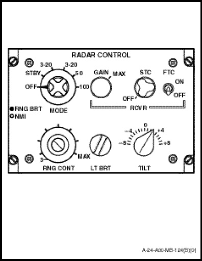
The RADAR CONTROL panel (Figure 1-11-3) controls the overall operation of the equipment.
Seven controls are mounted on the radar control. Each individual control and its function are described as follows:
WARNING
To avoid possible harmful effects from exposure to radio frequency radiation, personnel should not approach within 10 feet of the antenna when it is radiating and scanning and not within 50 feet when it is radiating and not scanning.
a. The MODE switch is a six-position rotaryswitch providing the following functions;
(1) OFF. In this position all power is disconnected, with the exception of the edge lighting 28 VDC supply, and the system is inoperative.
(2) STBY. In this position power is applied to the system with the transmitter inhibited. The indicator is selected into the 3 to 20 NM range with 10 mile range rings.
(3) 3-20. In this position the 3 to 20 NM range is selected, which can be manually adjusted by the RNG CONT control, together with 1 mile range rings. The transmitter becomes operative and remains operative throughout the remainder of the MODE switch positions.
(4) 3-20. In this position the system is selected as for the first 3-20 position with the exception that 5 mile range rings are selected.
(5) 50. In this position the 50 NM range is selected with 10 mile range rings.
(6) 100. In this position the 100 NM range is selected with 10 mile range rings.
b. The RNG CONT control is a dual-integral potentiometer providing the following functions;
(1) RNG BRT. Rotation of the inner control varies the brightness of the range rings.
(2) NMI. Rotation of the outer control varies the display range from 3 to 20 NM when the MODE switch is selected to either of the 3-20 positions.
c. The GAIN control is a rotary potentiometer which varies the intensity of the displayed video radar returns.
d. The STC control is a rotary potentiometer which is used to reduce sea clutter by decreasing receiver gain for close targets. It is variable from 0 to 20 NM and is set by turning the knob the desired amount to suit a particular situation. Because the STC reduces the effect of the GAIN control it should be in the CCW position whenever GAIN is being set.
e. The FTC control is an ON/OFF switch. When FTC is ON all video targets from the receiver are passed through a fast time constant circuit which allows only the leading edges of these targets to continue and be displayed on the radar indicator. The FTC is used to reduce clutter without reducing gain.
f. The LT BRT control is a rotary potentiometer which varies the panel illumination of the azimuth-range indicator, the range and bearing control panel and the radar set control.
g. The TILT control is a rotary potentiometer which controls the tilt angle of the antenna over a range +8 degrees to obtain optimum radar coverage.