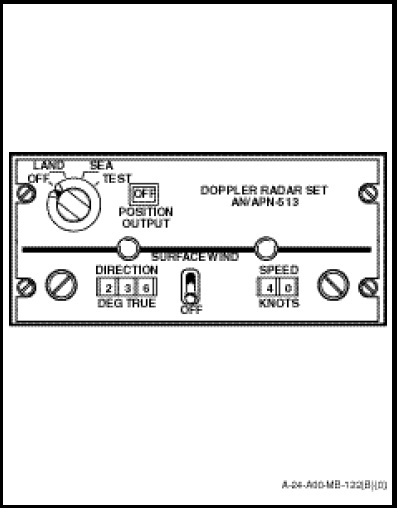
The doppler control panel (Figure 1-11-1) is located on the radio and navigation control panel and controls the overall operation of the equipment. The switches and indicators on the control panel are as follows:
a. Mode selector marked “OFF”, “LAND”, “SEA” and “TEST” with the following functions;
(1) OFF. In this position, the doppler system is inoperative.
(2) LAND. The doppler is operationally ready 2 minutes after this mode is selected. The velocity outputs are derived from the land scale factor.
(3) SEA. The operation of the doppler set with the mode selector in this position is similar to the LAND mode except that the velocity outputs are derived from the sea scale factor. The outputs are corrected for the effects of smooth water which distorts the return signal.
(4) TEST. A momentary-on position which initiates a self-test of the system and generates outputs and displays of test parameters for observation and verification.
b. POSITION OUTPUT. A red flag with the word OFF appears in the window to indicate loss of accurate navigation information while the green flag with the word ON indicates valid doppler information.
c. SURFACE WIND. The velocity correction which can be selected in the SEA mode of operation is contained on the lower half of the doppler control panel and marked “SURFACE WIND”. With the toggle switch in the up position, motion corrections may be inserted into the system. Speed, up to 99 knots, may be selected on the right counter using the right-hand control knob. Wind direction in degrees may be selected on the left-hand counter by the control knob on the left. The velocity correction may be used to remove the error in doppler velocity measurement caused by water motion.
NOTE
This feature, if left ON in a coupled hover will cause the doppler indicator to indicate incorrectly. To eliminate this error, the surface wind correction switch shall be selected to OFF prior to engaging the coupler.