The doppler radar set is a self contained airborne doppler radar system which provides continuous readouts of aircraft groundspeed and drift angles of up to 90 degrees to the left or right.
The doppler system also combines this information with GHARS generated signals of heading, pitch and roll to provide measured velocity data for the hover indicators as well as conditioned signals for the ASE, GHARS and ASN-123 systems.
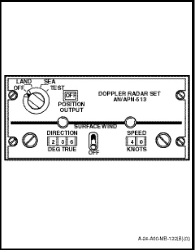
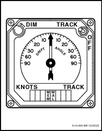
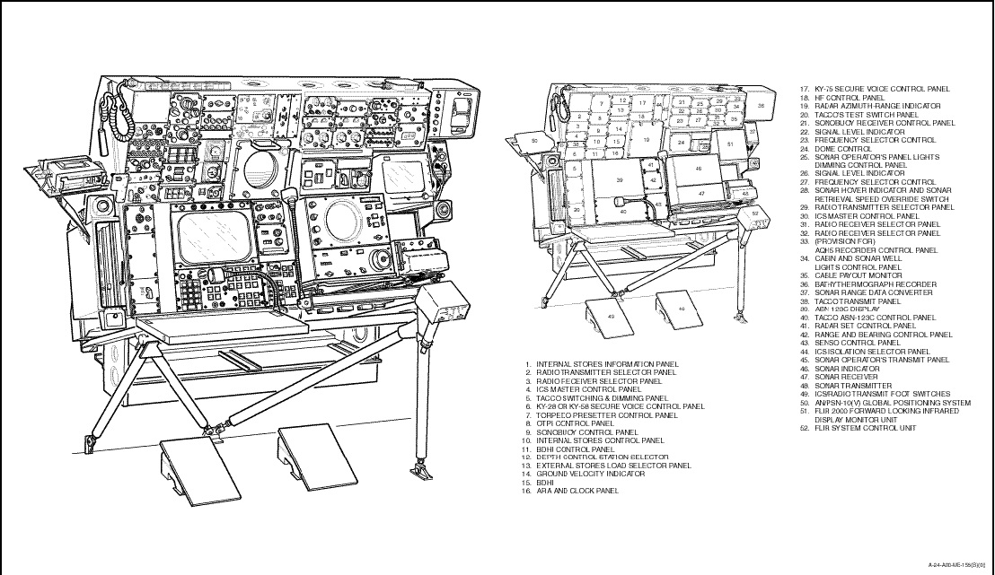
The radar navigation set consists of a combined receiver-transmitter and antenna unit located in the lower fuselage, a signal data converter mounted in the electronic compartment, a doppler control panel (Figure 1-11-1) located on the radio and navigation control panel and ground velocity indicators (Figure 1-11-2) on the instrument panel and the sensor station (Figure 1-10-9).
The doppler radar set operates on 115 VAC from the No.1 generator and 28 VDC from the No.2 radio bus. Both circuit-breakers are located on the radio circuit-breaker panel.
During SEA operation, the estimated surface wind speed and direction can be selected on the doppler control panel providing velocity correction for the doppler information.
If a loss of doppler signal should occur, the system will revert to a memory mode of operation and will display the last reliable information received. On acquisition of a useful doppler signal, the system will automatically return to normal operation.
NOTE
The DOPPLER UNRELIABLE light on the caution panel is connected to the failure warning system only when the ASE coupler is engaged and the CYC CPLR switch is in DOPP or Figure 1-11-1 Doppler Control Panel CABLE ANGLE.
When the doppler is in memory, the MEM annunciator on the Ground Velocity Indicator (GVI) will illuminate, the POSITION OUTPUT indicator on the control panel will indicate OFF, the hover indicator doppler OFF flag will be visible, the DOPPLER UNRELIABLE light on the caution panel will illuminate (if the ASE coupler is engaged) and the DOP light on the ASN-123 control indicator will illuminate. The ASN-123 will automatically convert from doppler to manual mode of operation, but retains the memorized wind data from the doppler system. The doppler system continues to supply latitude updating and convergency correction to the GHARS from its memory circuits, but if the helicopter heading or velocity change, the latitude updating and convergency correction become erroneous.
If the doppler system develops a malfunction, the MEM and MAL annunciators on the GVI will illuminate and all the indications associated with the doppler system reverting to the memory mode of operation will be present.
If the GHARS supplied signal of pitch and roll to the doppler system fails, the groundspeed display on the GVI will flash indicating the failure and the MAL annunciator will illuminate.
When the aircraft groundspeed is 10 knots or less, the TRACK displayed indicates aircraft heading, the groundspeed readout will indicate aircraft longitudinal velocity and the drift angle will read 0 degrees.