The HF transmitter-receiver provides two-way voice communication in the frequency range of 2.0 to 29.999 MHz. Limitations in the antenna coupler permit transmission only in the frequency range 2.0 to 23.0 MHz.
The HF radio set is protected by one DC and three AC circuit-breakers, marked “HF”, on the radio circuit-breaker panel and receives electrical power from the No.2 RADIO MASTER switch.
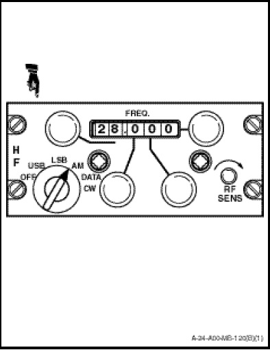
The HF is controlled from the panel, marked “HF” (Figure 1-10-18) on the centre of the TACCO/Sonar Operator station. The control functions are as follows:
a. The function selector switch is used to turn the HF set on and off and to select operating modes. Whenever the function selector switch is moved out of the OFF position, the HF will be turned on. The function selector has six positions with the following functions;
(1) OFF. HF system is disabled.
(2) USB. Selects an upper side band mode of operation.
(3) LSB. Selects a lower side band mode of operation.
(4) AM. Provides a mixing of the upper and lower side band frequencies so that communication with stations having only AM capability is possible.
(5) DATA. Used when it is desired to use auxiliary data equipment with the HF.
(6) CW. Provided for operation of the HF with a telegraph key.
NOTE
Positions DATA and CW are not used in this installation.
b. The MHz select knob, located to the left of the frequency indicator, is a 28-position rotary switch used to select HF radio frequencies from 2 to 29 MHz in 1.0 MHz steps.
c. The 0.1 MHz selector knob, located to the right of the function selector switch, is a 10-position rotary switch used to select HF frequencies from 0.0 to 0.9 MHz in 0.1 MHz steps.
d. The 0.01 MHz selector knob is located to the right of the 0.1 MHz selector knob and the 0.001 MHz selector knob is located to the right of the frequency indicator. The operation of the 0.01 and 0.001 MHz selector knobs is identical to the 0.1 selector knob.
e. The RF sensitivity control, marked “RF SENS”, is used to increase the RF gain to the HF radio set during receiver operation.
f. The FREQ indicator indicates the frequency selected by the selector knob.