The VHF/FM system provides two-way voice communications in the frequency range 150.0 to 173.9975 MHz in 2.5 KHz increments for a total of 9600 frequencies. The system incorporates a continuous duty cycle transmitter.
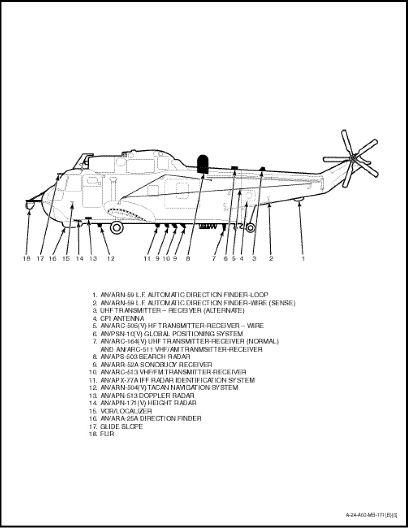
The system consists of three components: an antenna mounted just forward of the ASW chutes (Figure 1-9-1) on the lower fuselage, a transmitterreceiver located just above the HF transmitterreceiver and a set control located on the left-hand side of the radio and navigation control panel.
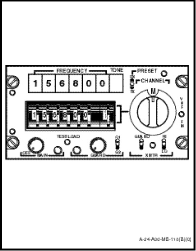
The set control (Figure 1-10-16) permits manual selection of frequencies over the range of the system or selection of one of 15 preset channels. A guard receiver with a choice of two preset frequencies can be monitored simultaneously with the main receiver. The set control incorporates the following controls:
a. MAIN Power Switch. Coupled to volume control of the main receiver. The set receives 28 VDC from the primary bus. It is protected by a 10 ampere circuit-breaker marked “VHF/FM” on the DC portion of the radio circuitbreaker panel.
b. MAIN Lamp. Lights up whenever the squelch of the main receiver is broken by a signal.
c. TEST/LOAD Switch. Dual function pushbutton used by technicians to program preset channels but can be used during normal operation to turn off the receiver squelch.
d. GUARD Lamp. Lights when signal is received on guard channel.
e. GUARD Volume. Volume control for guard receiver.
f. G1/G2 Switch. Two-position switch which allows for the selection of either one of the guard receiver frequencies.
g. XMTR/GUARD Switch. Two-position toggle switch which allows the transmitter frequency to be set either on the main frequency as selected on the thumb wheels or preset channel selector, or the same frequency to which the guard receiver is selected.
h. XMTR Light. Lights up when transmitting.
i. XMTR HI/LO Switch. Transmitter power switch which allows the selection of 10 watts or 1 watt RF output.
j. CHANNEL Selector. Allows selection of any 158 preset simplex or duplex channels or M for manual selection of a simplex only frequency of the thumb wheels.
NOTE
Simplex means two-way communications by transmitting and receiving on the same frequency. Duplex provides two-way communications using one frequency to transmit and a separate frequency to receive. This system is used on some marine and commercial telephone channels and allows simultaneously transmission and reception by the ground station. It will not provide simultaneously transmission and reception in the aircraft.
k. PRESET TX/RX Switch. Three-position toggle switch, spring loaded to the centre off position used to set up the preset channels. Can be used by the operator (by selecting TX) to check the frequency of the transmitter. This should only be different if a preset channel that has been set up for duplex is selected or if the XMTR/GUARD switch is in the GUARD position.
l. Thumb Wheels. Used to manually select a frequency for simplex operation of the set. (Thumb wheel on farthest right inoperative. Consequently, since switching is in 2.5 KHz steps, the last digit of 166.122 MHz frequency for example, is five, or 166.1225 MHz.)
NOTE
The thumb wheel on the farthest right allows for the selection of a sub-audible tone, indicated in the TONE portion of the digital readout window. It is used to trip tone coded squelches but is not functional on this system.
m. FREQUENCY. Digital readout of frequency to which the receiver is selected. Readouts read RX frequency when receiving the XMTR frequency when transmitting.
NOTE
Since VHF/FM transmissions cover the sonobuoy receiver frequency range, an interlock incorporated in the sonobuoy receiver main power switch disables the VHF/FM transmitter when the sonobuoy receivers are ON to prevent their desensitization.