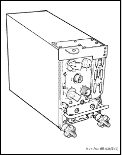
The KY-58 signal processor and the Z-AHQ interface adapter (Figure 1-10-13) form a unit and are located in the aft cabin, right side, upper avionics shelf. The control switches and functions of the signal processor basically duplicate the functions of the control panel and are as follows:
a. MODE Switch. A rotary switch for selecting plain (P) or ciphered (C) communications, for loading (LD) the fill registers and for receiving crypto-variables via radio transmission which is not used.
b. “FILL Switch. This switch, marked “Z1-5”, “1” through “6” and “Z ALL”, allows the loading of crypto-variables in the six registers. It also provides three options for zeroizing the registers. Registers 1 through 5 can be zeroized all at once by selecting Z1-5, each individual register can be zeroized individually by selecting the appropriate register or all six registers can be zeroized by selecting Z ALL.
NOTE
Register 6 is reserved for the rekeying variable used to encrypt remote keying for signal retransmission.
c. FILL Connector. Enables connection of either the KOI-18 or KYK-13 Common Fill Devices for coding of the crypto-variables.
d. VOLUME Control. Controls the output volume from the KY-58 to the ICS system.
e. POWER Switch. Marked “OFF”, “ON”, and “TD” is used to turn the system on and off, and enables a time delay in the KY-58 system for signal retransmission.
The control switches and functions of the Z-AHQ interface adapter are as follows:
a. Baseband Switch. This switch allows the selection of the type of radio used, normally in BBV for UHF operation.
b. Filter Switch. Baseband filter normally set to OUT.
c. REM-LOC Switch. A spring loaded switch, which allows the selection of remote or local operation and is used during the loading of crypto-variables codes into the KY-58.
d. PTT Switch. Used during the loading of crypto-variables into the KY-58. Once depressed the functional control of the system is returned to the remote control unit.
NOTES
1. When the TSEC/KY-58 signal processor is removed from the aircraft, a dummy connector shall be installed to complete the circuits for normal UHF and ICS operation.
2. When a complete TSEC/KY-58 system is installed, the POWER switch of the signal processor shall be selected ON and the MODE switch shall be selected to P for normal UHF and ICS operation.
3. When the complete TSEC/KY-58 system is installed, the POWER switch at the Z-AHP remote control panel shall be selected to ON and the C/RAD1, PLAIN switch shall be selected to PLAIN for normal UHF and ICS operation.